5
Kee!
sa il-
boat
Fin keel
-
mount forward
of the
keel,
ensuring
that the
keel will not
obstruct the transducers
wide beam
width
6
Keel
sail-
boat
Full keel
-
mount away from
the
keel at a location with minimum
dead rise, ensuring that the keel will
not obstruct the transducers wide
beam width
Location requirements
Follow
the
guidelines
below when selecting a location
for
your
single transducer or split-pair transducers.
For
best
performance,
transducers should be installed
in
a location with the Ieast turbulence and aeration.
lmportant: Do NOT install
transducers
in-line
with trailer rollers,
your
vessel's engine intake or
discharge openings.
Transducers
should be installed as close to the center
line
of
the vessel
as
possible.
The mounting
surface for the transducers should
be
flat
so that
the
supplied rubber
washer
sits
firmly
against the
hull.
When installing split-pair transducers with angled
elements,
you
must ensure that the hull's deadrise
angle at the chosen mounting location is appropriate
for the selected transducers. Refer to
the table in
Applicable
products.
The transducers should
be
installed away
from any
protrusions
such as other transducers,
steps, ribs,
strakes, or rows of rivets.
.
Transducers should be installed in a location where
no
load
will be applied to the
transducers
during,
launching, liftin9,
trailering and
storage
ofthe boat.
.
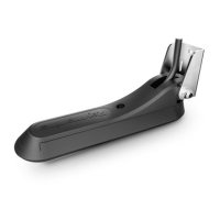
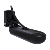
Transducers must be installed
in
the correct
orientation, with the anti-rotation bolt closest to the
stern of the vessel. Additionally,
a
dlrection arrow
pointing
to the
bow
is
embossed
on the anti-rotation
bolt cap. Refer to the the illustration in Mounting
-
RV-2x
bronze thru-hull,
which includes
a
"bow"
direction
arrow.
.
When installing
split-pair transducers:
-
the correct transducer
(port
or starboard) must be
installed in
the matching
(poft
or starboard)
side of
the hull; each transducer in a split
pair
has a
label
on
the attached cable, and markings and labels on the
transducer body to help
you
identify the transducer:
choose mounting
positions
that
are symmetric
about
the center line of the vessel.
e
@
Item Color
Description
1 Red Port-side split-pair transducer
cable
2 Green
Starboard-side split-pair
transducer cable
*#
o=x o._tr
@-
ffi
@-*
ffi
1 Planing
hull
Outboard ot llo
-
mount forward
and to the side of the
propelle(s)
2 PIaning
hull
lnboard
-
mount forward of the
propelle(s)
and shaft(s)
3 Planing
hull
Stepped hull
-
mount on the
first
step as
far
aft as
possible
4 Dis-
place-
ment
hull
Displacement hull
-
mount
approximately 1/3 of
the way along
the lenqth of
the
hull, measured
along the waterline
Step
2 Rib
3 Row of rivets
4
Strake
Item Description
1
Direction to vessel bow
2
Element angle and vessel side:
-
1"12"";
"2o"")
*
(port,
"P";
starboard,
"S")
Single
(all-in-one)
transducers are
marked
Vessel side
and direction
to vessel keel
Single
(all-in-one)
transducers omit
this label.
Dimension Measurement
H
308.O
mm
(12.13
in.)
105.3 mm
(4.15
in.)
-
choose
mounting
positions
that are at least 300 mm
('12
inches) below the water line.
Transducers should be installed
in
a
location where
there is sufficlent clearance
inside the hull to Iit the
nut and have at least 1OO mm
(4
in) of
headroom to
allow for withdrawal.
To avoid interference with the internal
magnetometer,
mount transducers at least 1 m
(39
inches) from other
electrical devices.
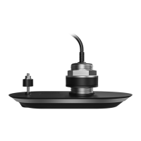
Transducer
dimensions
-
RV-2xx
All transducers in the RV-2xx series have the same
external dimensions.
.
RV-2OO attached cable length:
8 m
(26.2
ft).
.
RV-212(P/S) and RV-22O(P/S)
attached
cable length:
2 m
(6.5
ft).
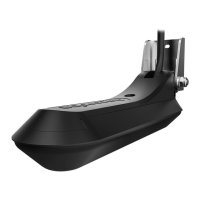
Mounting
-
RV-2xx bronze
thru-hull
This
procedure
applies
to all
transducers in
the
RV-2xx
series.
The following
procedure
should only be
performed
with
your
vessel out of the water.
lmportant:
.
Do NOT use the transducer cable to lift
or suspend
the transducer; always support the transducer
body directly during installation.
.
The threads on the Huli nut may be sharp,
ensure
that the supplied Cable
protector
is fitted to the
Hull nut before feeding the transducer cable
through the nut.
.
Do not remove
the
label
attached
to the
transducer
cable as it helps to ensure that connections
are
made correctly.
lmportant Wooden hulls may be
susceptible to
shrinkage
if the vessel is removed from the
water foI
an
extended
period,
followed by swelling
when the
vessel is returned to the
water
To avoid leaks or damage to the transducer
caused
by swelling:
.
ensure that the
vessel has been in the
water for
some time
immediately
prior
to removing
the
vessel
from the water and starting the transducer
installation.
.
when
you
have completed the
transducer
installation and
fully
tightened
the hull
nut and
anti-rotation
nut, return the vessel to
the water to
avoid
subsequent hull shrinkage.
rr*
-@
--*
{D
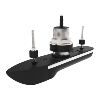
,|
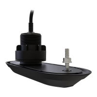
Hull
2 Anti-rotation nut
3 Bronze washer
4
Transducer cable
5
Hull nut
Dimension Measurement
A
727mm
(2.a6
in.)
B
6O.0
mm
(2.36
in.)
c 85.O mm
(3.35
in.)
D
8.o mm
(0.31
in.)
E
80.o mm
(3.15
in.)
F
3Ol mm
(1.19
in.)
G 1o9.o mm
(4.29
in.l
 Loading...