Do you have a question about the Raymarine RV-100 RealVision 3D and is the answer not in the manual?
Access the latest and complete documentation and safety information from the Raymarine website.
Certified installation by approved installers qualifies for enhanced product warranty benefits.
Product compliance with EMC directive 2004/108/EC as declared by Raymarine UK Ltd.
Register your Raymarine product online via the website for full warranty benefits.
Dispose of the product in accordance with the Waste Electrical and Electronic Equipment Directive.
Equipment is intended for leisure marine boats and workboats not covered by IMO/SOLAS regulations.
Information was correct at time of production; check website for latest versions.
Lists the necessary tools for installing the transducer, such as a power drill and sealant.
Check transducer operation before installation by connecting, submerging, and powering up.
Mount near keel, away from propellers, considering turbulence and vessel movement.
Fix template, ensure parallelism, drill two holes for adjustment screws, apply sealant.
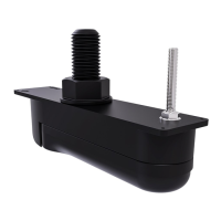
Position hanger between bracket arms, secure with bolt and nut, hand-tighten.
Align hanger for parallel bottom face to waterline, tighten bolt firmly.
Route cable away from VHF, ensure sufficient length and slack, secure with clips.
Use escutcheon plate to cover 25 mm hole for cable, ensure no trapping.
Slide the locking collar over the connector end, ensuring lugs are closest to the plug-end.
Slide the split-ring over the connector end, ensuring tabs are closest to the cable-end.
Use the supplied tool to lever the split-ring over the connector moulding to secure it.
Slide the O-ring over the connector end, ensuring it seats squarely against the moulding.
Slide and rotate the locking collar so its lugs pass through the split-ring channels.
Grasp the connector and pull the locking collar firmly towards the plug-end until it clicks.
Ensure power is off, push connector fully, turn locking collar clockwise to secure.
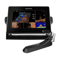
Test in water with depth > 0.7m, open Sonar app, check readings and image.
Make small incremental adjustments, re-test until optimum performance is achieved.
Drill locking hole, fill with sealant, tighten mounting screws and bolt to final position.
| Brand | Raymarine |
|---|---|
| Model | RV-100 RealVision 3D |
| Category | Transducer |
| Language | English |