Do you have a question about the Raymarine AUTOHELM ST50 PLUS DEPTH and is the answer not in the manual?
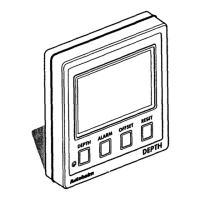
Details the recommended siting for optimal readability and protection against damage.
Step-by-step guide for bulkhead and bracket mounting, including template use and cable routing.
Explains standalone and SeaTalk power supply connection methods for the instrument.
Details connecting other instruments using SeaTalk extension cables or alternative screened cable.
Guidance on ring-main connections for systems with many instruments to prevent voltage drops.
Describes connecting the ST50 instruments to a SeaTalk compatible autopilot system.
Explains connecting the depth transducer via SeaTalk connector to the control head.
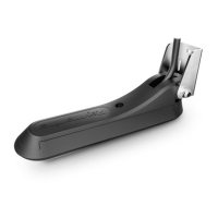
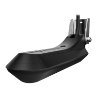
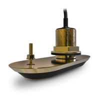
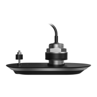
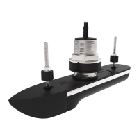
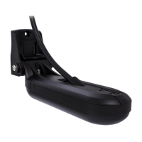
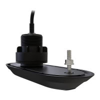
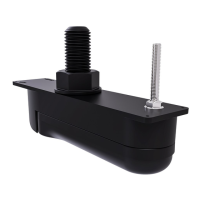
Guides selection of the correct depth transducer based on hull material.
Covers transducer installation, optimal siting for accurate readings, and proper cabling.
Table of common faults, their causes, and recommended actions for troubleshooting.
Guidance on maintaining the instrument, transducer, and cabling for optimal performance.
Explains the functions and operation of the DEPTH key for various settings.
Details the operation of the ALARM key for managing shallow, deep, and anchor alarms.
Describes how to use the OFFSET key to adjust depth measurement relative to the waterline.
Explains the function of the RESET key for toggling depth units between feet and metres.
Instructions for adjusting display contrast for optimal legibility at different viewing angles.
Explains operating the system requiring code entry each time it is powered on.
Procedure for enabling and setting the four-digit security code for the first time.
Steps to follow when powering up the unit for initial calibration and code entry.
Guides through setting alarms, units, and offsets for the first time.
Explains settings for repeater mode and security configuration.
Covers advanced settings like depth damping and the dealer demonstration 'Boat Show' mode.
| power supply | 10 to 16 V |
|---|---|
| power consumption | 100 mA |
| illumination levels | 3 levels plus off |
| temperature range | 0 to 70 °C |
|---|---|
| shallow alarm | 10 to 400 feet (3 to 120 metres) |
| deep alarm | 0 to 600 feet (0 to 180 metres) |
| dimensions | 110x110 mm (4.33x4.33 in) |
|---|---|
| depth | 0 to 600 feet (0 to 180 metres) |
| minimum depth | 3 to 33 feet (1 to 10 metres) |