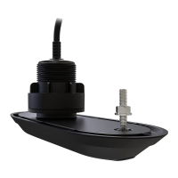
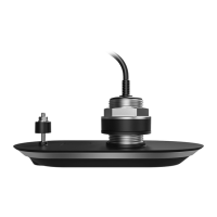
Testingthetransducer
Transduceroperationshouldbecheckedbeforeinstallation.
1.Connectthetransducertothemultifunctiondisplay’stransducerconnection.
2.Fullysubmergethetransducerinwater.
3.Powerupthedisplay.
4.OpenaFishfinderapplicationonyourdisplay.
5.Ifrequired,selecttherelevanttransducer/channelfromtheChannelselectionpage(
Menu>
Channel).
6.Checkthataccuratedepthandtemperaturereadingsaredisplayed.
7.IfyouexperiencedifficultiesobtainingreadingsthencontactRaymarineT echnicalSupport.
Warning:Transduceroperation
Onlytestandoperatethetransducerinthewater.DoNOToperateoutofwater
asoverheatingmayoccur.
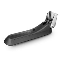
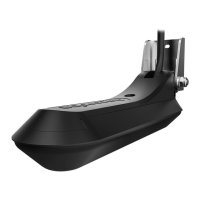
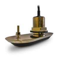
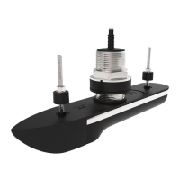
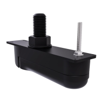
Selectingalocationforthetransducer
Theguidelinesbelowshouldbefollowedwhenselectingalocationforthetransducer.
Note:Thetransducerisnotsuitableformountingonvesselswherethetransomisaftofthe
propeller(s).
Forbestperformancethetransducermustbeinstalledinalocationwiththeleastturbulenceand
aeration.Themosteffectivewaytodeterminethisisbycheckingthewaterflowaroundthetransom
whilstunderway.
•Mountclosetothekeel(centerline),inapositionwherethetransducerelementwillbefully
submergedwhenthevesselisplaningandturning.
•Mountasuitabledistancefromthepropeller(s)toavoidwake.
•Mountinalocationwherenoloadwillbeappliedtothetransducerduringlaunching,lifting,
traileringandstorageoftheboat.
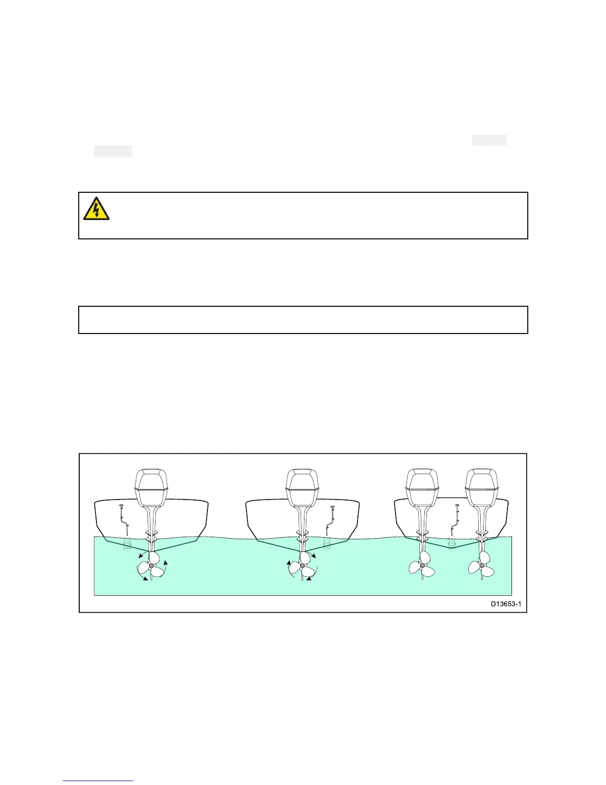
•Forclockwiserotatingpropellers,mountthetransduceronthestarboardside,for
counter-clockwise,mountontheportside.
•Onatwinenginevesselmountthetransducerbetweentheengines.
•Turbulencecanbecausedbyanumberofotherfactorssuchassteps(1),ribs(2),rowsofrivets(3)
andstrakes(4).Theturbulenceappearsaftoftheselocations.
7
 Loading...