Do you have a question about the Raynor ControlHoist 2.0 STANDARD and is the answer not in the manual?
Specifies the necessary headroom and side clearance for operator installation.
Details compatible door types and the operator's reduction and motor specifications.
Covers frequency of operation, motor details, and control circuit information.
Highlights the adjustable friction clutch and overload protection.
Identifies the type of limit switches used for door control.
Crucial safety warning regarding severe personal injury or death if instructions are not followed.
Emphasizes the necessity of reading and adhering to all installation steps.
Instructions for checking shipping container and operator parts for damage.
Covers unpacking and critical mounting position guidelines for installation.
Diagram and instructions for CSH model brake disconnect chain.
Diagram and instructions for CSJ model drive disconnect chain.
Critical safety instruction for photo eye installation height, must be <= 6".
Serious warning about using unapproved reversing devices and table for monitored devices.
Tables detailing minimum wire gauge for single-phase and three-phase motors based on distance and HP.
Critical safety directive to disconnect power before clutch adjustment.
Warning against over-tensioning the clutch to prevent damage or injury.
Diagram illustrating the logic board layout and terminal connections.
Diagram showing the optional auxiliary board and its connections.
Key notes for programming the logic board, including button usage.
Instructions for selecting the appropriate wiring mode for the operator.
Guide for setting the type of the first and second sensor inputs.
Instructions for adjusting the maximum run timer to prevent operator damage.
Procedure for switching open/close limits and reversing motor direction.
Overarching safety warning for users of the operator regarding injury or death.
Instructions on how to operate the door using the standard 3-button control.
Steps to check and verify the correct adjustment of limit switches.
Procedure for testing safety features like photo eyes and reversing edges.
Information on lubrication requirements and general inspection of the operator.
Guidance on repairs by qualified installers and caution regarding overload reset.
Definitions for Stop, Open, and Close status lights indicating button status.
Definitions for Sensor 1/2 and I-Lock status lights indicating their states.
Definitions for Single, Aux Input, and Limit switch status lights.
Explanations for common LCD messages like "Locked Out", "TCS Paused", etc.
Definitions for messages indicating door movement or status like "Partially Open".
Troubleshooting steps for when the operator does not respond to commands.
Troubleshooting for constant pressure operation or reversed motor direction.
Troubleshooting steps for limit switch non-operation and maximum run timer problems.
Troubleshooting for sensor signal problems and normal operation delays.
Warning about running high voltage wires near low voltage wiring to prevent interference.
Instructions and warnings for connecting external accessories to the logic board.
Information on auxiliary board contact ratings and relay usage for higher loads.
Placement guidance for push button placards and disconnect instruction labels.
Placement guidance for door safety labels, danger labels, and spring warning tags.
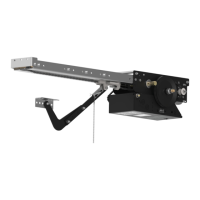
The Raynor ControlHoist 2.0 Standard Jackshaft type electric operator is designed for use on commercial and industrial size sectional overhead doors and rolling doors only. It is intended for indoor use and not for residential applications.
The device is an industrial-duty electric operator for overhead doors, available in two models: CSJ (Jackshaft) and CSH (Jackshaft with Chain Hoist). It utilizes a V-belt drive from the motor to a full ball bearing power train, with additional chain and sprocket reduction for door movement. The operator is designed to move the door at a speed of 6 to 12 inches per second, depending on door size, sprocket reduction, and track type. It can handle up to 30 cycles per hour or 300 cycles per day.
| Brand | Raynor |
|---|---|
| Model | ControlHoist 2.0 STANDARD |
| Category | Door Opening System |
| Language | English |