10
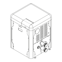
5.2. Clearances
5.2.1. All Heaters
For indoor and outdoors clearances from combustible
surfaces, see the chart below.
Location Indoor Installation
Top * 30" (762 mm) Drafthood
Front Alcove (Open)
Vent 6" (152 mm)
Floor ** 0"
Back 6" (152 mm)
Right Side 12" (305 mm) Water Side
Left Side 6" (152 mm) Opposite Water Side
Location Outdoor Installation
Top * Unobstructed (Outdoor Stack)
Top *** 36" (76 mm) (Stackless Top)
Right Side 12" (305 mm) Water Side
Left Side 6" (152 mm)
Floor 0"
Back 6" (152 mm)
* Clearance from top of vent terminal
** Do not install on carpeting
*** Clearance from top of heater
Table B. Minimum Clearances from Combustible Installations
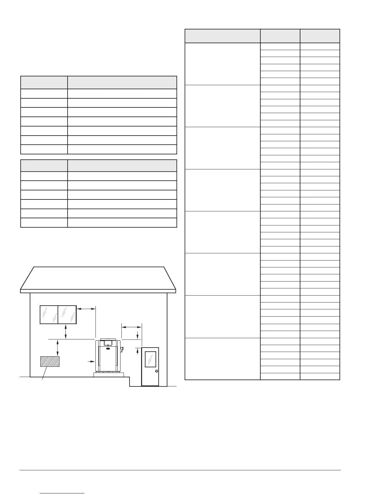
Forced Air Inlet
4' (1.2 m)
Minimum
3' (0.9 m)
Minimum
10' (3 m)
Minimum
1' (0.3 m)
Minimum
4' (1.2 m)
Minimum
4' (1.2 m)
Minimum
Figure 4. Minimum Distances to Building Openings from
Where Flue Products Exit the Boiler
Description Location
Distance
in. (mm)
a. 3-1/2" (89 mm) thick
masonry walls without
ventilated air space
Back 9 (229)
Right 9 (229)
Left 9 (229)
Vent 5 (127)
Indoor Top 39 (991)
Outdoor Top Unobstructed
b. 1/2" (13 mm)insulation
board over 1" (25 mm)
glass ber or mineral
wool batts
Back 6 (152)
Right 6 (152)
Left 6 (152)
Vent 3 (76)
Indoor Top 30 (762)
Outdoor Top Unobstructed
c. 0.024 sheet metal over
1" (25 mm) glass ber
or mineral wool batts
reinforced with wire on
rear face with ventilated
air space
Back 4 (102)
Right 4 (102)
Left 4 (102)
Vent 3 (76)
Indoor Top 24 (610)
Outdoor Top Unobstructed
d. 3-1/2" (89 mm) thick
masonry wall with
ventilated air space
Back 6 (152)
Right 6 (152)
Left 6 (152)
Vent 6 (152)
Indoor Top 39 (991)
Outdoor Top Unobstructed
e. 0.024 sheet metal with
ventilated air space
Back 4 (102)
Right 4 (102)
Left 4 (102)
Vent 2 (51)
Indoor Top 24 (610)
Outdoor Top Unobstructed
f. 1/2" (13 mm) thick
insulation board with
ventilated air space
Back 4 (102)
Right 4 (102)
Left 4 (102)
Vent 3 (76)
Indoor Top 24 (610)
Outdoor Top Unobstructed
g. 0.024 sheet metal with
ventilated air space over
0.024 sheet metal with
ventilated air space.
Back 4 (102)
Right 4 (102)
Left 4 (102)
Vent 3 (76)
Indoor Top 24 (610)
Outdoor Top Unobstructed
h. 1" (25 mm) glass ber
or mineral wool batts
sandwiched between
two sheets 0.024 sheet
metal with ventilated air
space
Back 4 (102)
Right 4 (102)
Left 4 (102)
Vent 3 (76)
Indoor Top 24 (610)
Outdoor Top Unobstructed
Derived from National Fuel Gas Code, Table 10.2.3
Table C. Reduction of Clearances to Protected Surfaces
When installed according to the listed minimum clearances
from combustible construction, the pool heater can still
be serviced without removing permanent construction
around the heater.
However for ease of servicing, we recommend a clearance
of at least 24" (610 mm) in the front, and at least 18" (457
mm) on the water connection side.