29
Wire Nut -
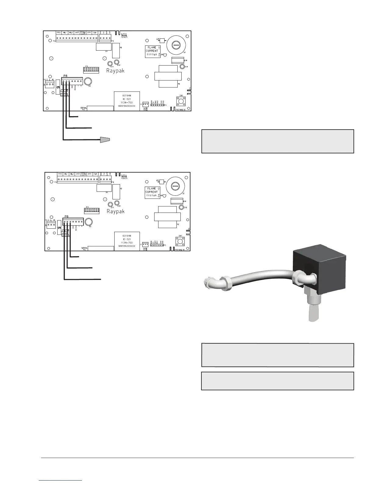
BLK/ORN - To Pool (COMM)
ORN/BLK - To Spa (COMM)
BLU - 24VAC
Figure 44. 2-Wire Remote Harness Installation on the P8
Connector of the ATF Board
BLK/ORN - To Pool (COMM)
ORN/BLK - To Spa (COMM)
BLU - 24VAC
Figure 45. 3-Wire Remote Harness Installation on the P8
Connector of the ATF Board
4. On the “Remote Interface Harness” connect the
BLUE wire to one side of the “REMOTE” switch
and connect the ORANGE/BLACK wire for “SPA”
operation and the BLACK/ORANGE wire for the
“POOL” operation. See Figure 43.
5. Install the “Remote Interface Harness” to the P8
connector and turn power “ON” to the heater.
SeeFigure 45.
6. For activation of the remote control, see section 8.4.3
on page 28.
8.5.3. Time Clock/Fireman’s Switch
To operate the heater with a time clock, connect the timer
to the reman’s switch connection in the heater’s wiring.
The time clock should be of the dual switch type and set to
shut o the call for heat to the pool heater (chaue-piscine)
15 to 20 minutes prior to shutting down the pool pump.
On heaters, splice into the red/white wire to connect the
time clock. For heaters the reman’s switch connection
is located on the 14-pin header connected to the digital
control board. Splice into the red wire jumper tagged
“Where necessary add “Fireman’s” switch circuit here” to
connect the time clock.
The reman’s switch connection on both heaters
must be a dry contact and must not supply power to
the heater. Powering the reman’s switch connection
externally may damage the heater, and is not covered
by warranty.
Do not exceed 50' (15.2 m) of total wiring using 18 AWG
stranded copper wire rated for 221°F (105°C) minimum.
NOTE: When using a time clock, the heater will display
“Clock/Fireman Sw” when the reman’s switch is open,
indicating that the time clock has shut o the call for heat.
8.5.4. Water Flow Switch
The water ow switch ensures that the heater operates
only when the lter pump is in operation. It is located on
the outlet side of the In/Out header. It is factory pre-wired
and pre-set with a minimum water ow paddle. Install
conduit to the upper jacket hole. Connect two wires from
the conduit to the appropriate terminal wires behind the
transformer cover (i.e. orange to orange and orange/black
to orange/black). No further adjustment is needed.
Figure 46. Water Flow Switch Assembly
NOTE: The sheet metal cover should be in place at all
times to protect the ow switch from rain and other
environmental factors.
AA
CAUTION: Do not operate the heater without the
function of a properly adjusted ow switch.