EasyManua.ls Logo

Raypak LONMARK Y-200 User Manual

Raypak LONMARK Y-200
40 pages
To Next Page IconTo Next Page
Page #1 background imageLoading...
Page #1 background image
INSTALLATION & OPERATING
INSTRUCTIONS
Catalog No. 5000.62H Effective: 09-28-09 Replaces: 11-25-08 P/N 241125 Rev. 9
Y-200 Series
Electronic Boiler Sequencer & Outdoor
Reset Control System
Question and Answer IconNeed help?

Do you have a question about the Raypak LONMARK Y-200 and is the answer not in the manual?

Raypak LONMARK Y-200 Specifications

General IconGeneral
BrandRaypak
ModelLONMARK Y-200
CategoryController
LanguageEnglish

Summary

Safety and Introduction to Y-200 Control

Safety Instructions and Precautions

Instructions for qualified personnel, warnings, and cautions regarding installation and service.

Controller Models and Options

Y-200 Controller Configurations

Details different Y-200 models (Y-241, Y-281) and their stage configurations.

Installation Procedures

Mechanical and Electrical Installation

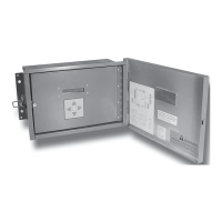
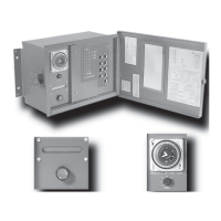
Guidance on mounting location, physical installation, and electrical wiring requirements.

Power Source Verification

Procedure to verify incoming voltage levels using a volt-ohm meter before connection.

Wiring and Power Connections

Controller Power Requirements and Safety

Key electrical safety notes and connection points for powering the controller.

Boiler Field Wiring Diagrams

Wiring instructions for single-stage and multiple-stage boiler configurations.

Sensor and Communication Wiring

RS485 Communication Wiring for Slaves

Details on wiring slave units using RS485 communication for master/slave systems.

Water Temperature Sensor Installation

Installation Verification and System Basics

Installation Verification Checklist

Checklist to ensure all installation steps have been completed correctly.

Control Screen Configuration and Parameters

System Monitoring, Status, and Control Settings

System Testing, Defaults, and Alarms

Master/Slave Configuration Basics

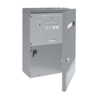
Configuration for the master unit and stage/sensor connection details.

Networked System Configuration

Master/Slave Network Setup

Steps to configure the master unit and connect slave units for network operation.

System Diagrams and Parts Reference

Y-200 Master/Slave Wiring Diagram

Visual representation of wiring connections between master and slave controllers.

Sensor Resistance Testing Procedure

Guide to testing sensor resistance values for troubleshooting sensor errors.

Related product manuals