9
7. Bond permanently-wired pumps. The National
Electrical Code requires that the motor be electrically
bonded to the appropriate permanently-installed
pool or spa/hot tub structure using a solid copper
conductor no smaller than No. 8 AWG. The bonding
wire should be connected from the accessible wire
connector on the motor shell to all metal parts of the
swimming pool, spa or hot tub structure and to all
electrical equipment, metal conduit and metal piping
within 5 feet of the inside walls of a swimming pool,
spa or hot tub. A grounding lug is provided on the
exterior of the motor shell for this purpose.
Filter Assembly
Common tools such as screwdrivers, wrenches, and
consumables like pipe sealant for plastic adapters are
required for the installation and service of the sand lter.
See the schematic for layout information, Figure 4.
Pouring Sand Filter Sand Media
1. The filter should be placed on a level concrete slab,
very firm ground, or equivalent. Locate the filter
so that the piping connections, control valve are
convenient and accessible for operation and service.
2. Filter sand media is loaded through the top opening
of the filter as follows:
a. Loosen the flange clamp and remove the filter
control valve (if previously installed).
b. Cap the internal pipe with a plastic cap to prevent
sand from entering it.
c. We recommend filling the tank approximately 1/2
full with water to provide a cushioning effect when
the filter sand is poured in. This helps protect the
under-drain laterals from excessive shock.
d. Carefully pour in the correct amount and grade
of filter sand. (Be sure the center pipe remains
centered in opening.) When done, the sand
surface should be leveled and should come to
about the middle of the filter tank. Remove the
plastic cap from the internal pipe.
Filter Control Valve Assembly
1. Assemble the filter control valve in the filter tank.
a. Insert the filter control valve (with O-ring in place)
into the tank neck, taking care that the center
pipe slips into the hole at the bottom of the valve.
b. Place two plastic clamps around the valve flange
and tank flange and tighten just enough so that
the valve may be rotated on the tank for final
positioning.
c. Carefully screw the pressure gauge (with O-ring
in place) into the tapped hole in the valve body.
Do not over-tighten.
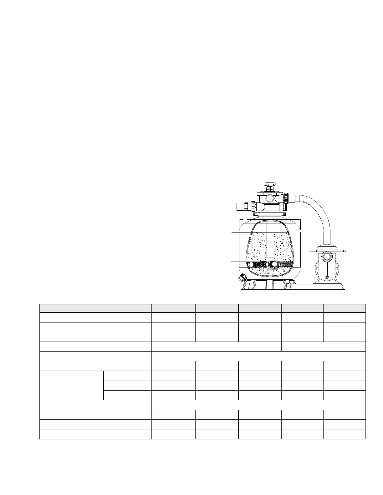
C
B
Figure 2. Dimensions
Combo Model RPSFP16 RPSFP18 RPSFP21 RPSFP181 RPSFP211
Filter Model RPSF16 RPSF18 RFSF21 RPSF18 RFSF21
Pump Model RPAGP75 RPAGP100 RPAGP150 RPAGP102 RPAGP152
Power (HP) 0.75 1 1.5 1 1.5
Speed Single Dual
Max Operating Pressure, PSI (bar) 28 (2)
Max Flow Rate Pump + Filter, GPM (LPM) 50 (187) 63 (237) 68 (258) 63 (237) 68 (258)
Turnover Rate, Gal. (L)
2 Hours 6000 (22680) 7560 (28577) 8160 (30845) 7560 (28577) 8160 (30845)
4 Hours 12000 (45360) 15120 (57154) 16320 (61690) 15120 (57154) 16320 (61690)
6 Hours 18000 (68040) 22680 (85731) 24480 (92535) 22680 (85731) 24480 (92535)
Valve Port 1.5"
Filter Dia., in (mm), "B" 15.7 (399) 17.7 (450) 20.7 (526) 17.7 (450) 20.7 (526)
Silica Height, in (mm), "C" 6.9 (175) 8.3 (211) 9.3 (235) 8.3 (211) 9.3 (235)
Silica 16/30* Weight, lb (kg) 77 (35) 99 (45) 209 (95) 99 (45) 209 (95)
*Suggested silica weight is for reference only and based on recommended filter media. Weight will vary based on type and size of media used.
Recommended Filter Media: 16/30 Mesh Silica Sand / Silica #20 (0.5 - 0.8mm diameter)
Table A. Specications