16
Connecting the Controller
Apply power to the Controller. The operation of the
Controller on power up is described in the Sequence
of Operation section, starting on page 4 of this manu-
al.
Testing the Controller’s
Outputs
The Controller has a built-in test routine, which is used
to test the main control functions. The test sequence is
enabled when the ▲ button is pressed and held for 3
seconds while in the View menu. The outputs are test-
ed in the following sequence:
1. After 1 second, the pump is turned on.
2. After 4 seconds, Stage 1 is turned on.
3. After 7 seconds, Stage 2 is turned on.
4. After 10 seconds, Stage 3 is turned on.
Fig. 22: Testing the Controller’s Outputs
Sensor Resistance
Temperature (°
°°
°F)
Resistance (Ω)
-50 490,813
-40 336,606
-30 234,196
-20 165,180
-10 118,018
0 85,362
10 62,465
20 46,218
30 34,558
40 26,099
50 19,900
60 15,311
70 11,883
77 10,000
80 9,299
90 7,334
100 5,828
110 4,665
120 3,760
130 3,050
140 2,490
150 2,045
160 1,689
170 1,403
180 1,172
190 983
200 829
210 703
220 598
Table D: Sensor Resistance
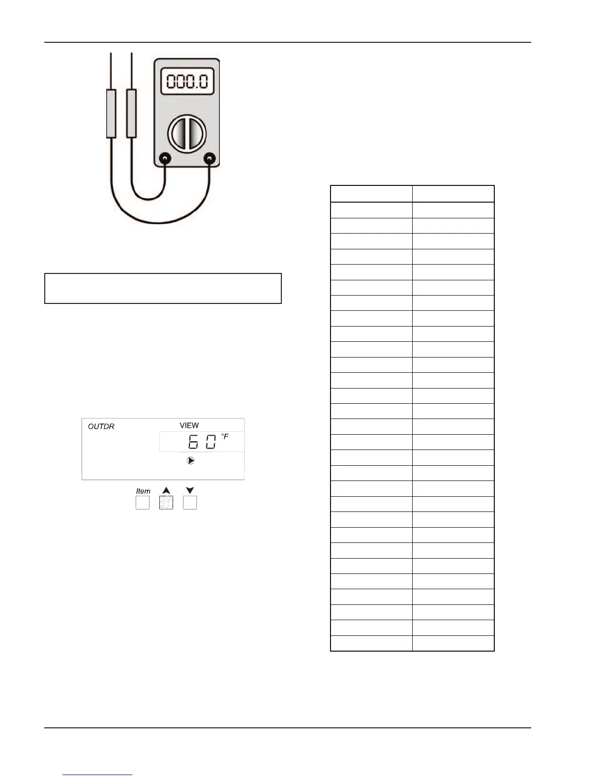
NOTE: Make sure ALL power to the devices and
wiring harness is off.
Fig. 21: Multi-meter
5
. After 13 seconds, Stage 4 is turned on.
6. After 16 seconds, the pump and stages 1 to 4 are
shut off. The alarm contacts are closed for 10 sec-
o
nds.
7
. The control exits the test sequence and resumes
normal operation.