19
CONTROLLER
SETTINGS
T
ables F through T describe the “View” and “Adjust”
menus. They also show the default settings as well
as any possible adjustment ranges.
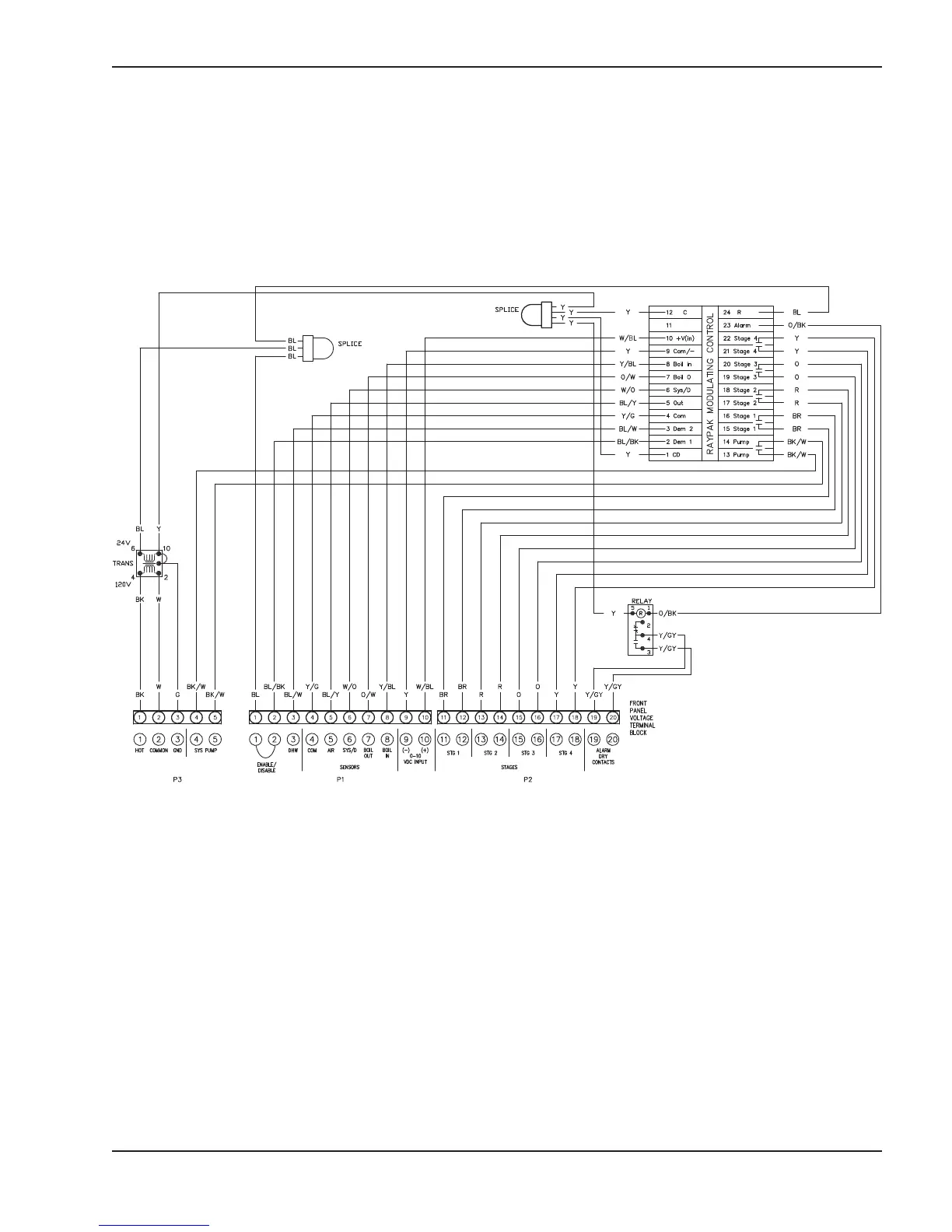
Fig. 25: Wiring Diagram (Field Installation)
Field Installation
Field wiring must be connected to the terminal block
o
n the back side of the controller mounting bracket.
Follow the wiring diagram as specified in Fig. 25
below.