OPTIONAL FEATURES HeatNet Control V3
Page 63
Combustion Air Damper
Relay K5 and the terminal J13 DAMPER is used to control a
combustion air damper. J12B.7 & .8 are used to detect the dry
contact proof switch from the damper. A proof time of up to 4
minutes can be set before the boiler can start or an alarm
condition will occur. The Combustion Damper can be setup in
the SETTINGS: COMBUSTION AIR DAMPER menu.
Using the LINKED/COMMON setting, the Master boiler
controls a system damper, so in the event this damper fails to
open, the system will not start. If the Master boiler’s system
damper fails, then no call for heat will be made to the member
boiler(s).
Using the INDEPENDENT setting, each member boiler can
control its own damper and is independent of the Master
boiler when a call for heat is made to the member. This allows
for separate dampers for each boiler. They can be wired to
J12B terminals 7 and 8.
If a common system damper is used (controlled by the Master
boiler), each individual boiler must prove that the combustion
air damper is open when it is placed in LOCAL. This may be
done using J12B terminal 7 on all boilers wired to the
damper’s prove switch. Terminal 7 is the sense input and
terminal 8 is 24 VAC. Connecting a wire to terminal 8 is not
recommended.
See Figure 58, Common system damper wiring, Page 83.
A separate/independent 24 VAC source is
recommended to be used for the damper prove
switch when a common system damper is used.
If you use terminal 8 to supply power from the
Master and the Master is powered OFF, no
boiler will be allowed to fire due to the loss of
power through the prove switch. A backup
boiler will also need to have the damper relay
contacts wired in parallel with the Master for
when the Master is powered OFF.
A second wire on the Master J12B terminal 7 is then
connected. The other end of this wire is then run to the first
Member boiler J12B terminal 7. If another member boiler is
present, a second wire can be connected to the first member
boiler J12B terminal 7 and the other end connected to the
other boiler J12 terminal 7. This method can be continued if
additional boilers are present. This input must be selected in
the SETTINGS: COMBUSTION AIR DAMPER menu.
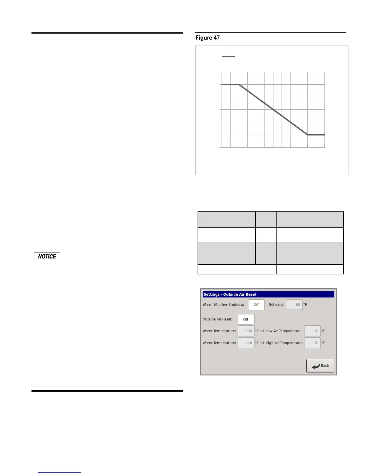
Outdoor Reset
The Outdoor reset feature allows the water setpoint
temperature to change dynamically with the outside air
temperature. It also provides an adjustable temperature that
shuts the boiler (or boiler system) down when the outside
temperature rises above it.
Outdoor reset curve, typical
The above chart shows how the water temperature setpoint
changes with the Outside air temperature. The four values of
180, 10 and 140, 70 are the default values:
Water temp @
outside air temp
Water temp @
outside air temp
Outside air temperature
where Warm Weather
Shutdown occurs
The chart depicts what the water temperature setpoint will
equal with a corresponding outside air temperature. At an
outside temperature of 10F and below, the water temperature
setpoint will be limited to 180F. With an outdoor temperature
of 70F and above, the water temperature will be limited to
140F. The water temperature setpoint will track along the
charts plotted line with corresponding outside temperatures.
130
140
150
160
170
180
190
10 70
Water Temp
Outside Temp
WATER TEMPERATURE SETPOINT
 Loading...


