31
Cast Iron Condensing Boilers – Installation Manual
FlexCore Stainless Steel Condensing Boilers – Installation Manual
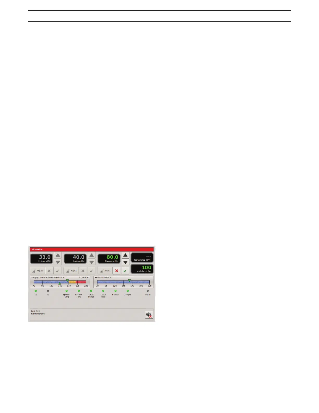
b. Press the ‘Adjust’ button under the Minimum (%)
setting. The percentage value will turn green. Adjust
the minimum value (%), using the arrow keys, to
achieve the required combustion - C02/02, (Table
11), and pressure – delta p, (Table 12), at low fire
based on the desired turn down.
c. Adjust low fire 02-C02 by opening the low fire
adjustment door located on the forward facing side
of the main gas valve, (Figure 17). Inserting an allen
wrench and rotating the allen screw clock-wise will
increase the C02 and lower the 02; rotating counter
clock-wise will decrease the C02 and increase the 02.
d. When the adjustment is satisfactory, press the
check key to save the setting.
26. Setting the Max VFD and High Fire Combustion
values: Remove the demand from the 7800 control by
disabling the low fire switch allowing the boiler to stop.
a. Verify the ‘S2’- Calibration switch located on the
3.0 HeatNet board is in the ‘CAL’ position. While
in Stanby (no call for heat on inputs), the Max
VFD percentage may be preset, before firing
the boiler. Press the 'Adjust' button under the
Maximum (%) setting and set this value to a lower
input value (50%). This will allow for manual input
control during the high fire set up process (26b.).
When the adjustment is satisfactory press the
check key to save the setting. Follow the same
procedure for the middle and rear module on units
(CK3500 - CK9000).
b. Using the low fire switch on the HeatNet board
create a minimum input demand. The boiler
will cycle to low fire position. Press the ‘Adjust’
button under the Maximum (%) setting. Boiler
input will modulate to the previously set (50%)
input. The percentage value will turn green
indicating that it can be changed. Adjust the
maximum value (%), using the arrow keys, to
achieve the required combustion – CO2/O2
(Table 11), and pressure – delta p, (Table 12).
c. The high fire trim adjustment is located on the
outlet flange, (Figure 17), of the gas valve.
d. When the adjustment is satisfactory press the
check key to save the setting. Follow the same
procedure for the middle and rear modules on
units (CK3500-CK9000). When complete, place
the ‘S2’ switch back to the ‘NORM’ position.
e. Allow the boiler to settle into min input and observe
combustion and pressure-delta p readings to
ensure the boiler is operating correctly. Make any
required adjustments. When complete disable the
low fire hold switch.
f. Follow the instructions in the HeatNet Control
manual to allow adjustments required for high
altitude installations.
SEQUENCE OF OPERATION
NO DEMAND
Standby
1. The boiler is idle with no interlocks in the fault condition.
DEMAND
Pre-Purge
1. The blower operates at purge RPM. The water flow
interlock must ‘make’ within 15 seconds after the
demand signal is initiated.
2. The Honeywell 7800 starts a 10 second purge delay
once the air prove switch contacts close.
Pilot Run - %Input
1. The blower operates at minimum ignition setting.
See the calibration section in the "FlexCore Series
Control IOM" to enter the calibration menus.
2. The ignition transformer is energized. The pilot solenoid
valve opens for the 10 second pilot ignition trial.
Main Run %Input
1. The main gas valve opens.
2. The ignition transformer is de-energized.
3. The pilot solenoid valve closes.
4. The blower stays at the minimum input setting for
3 seconds then operates at demand % input. See
the calibration section in the "FlexCore Series
Control-IOM" to enter the calibration menus.
NO DEMAND
Post-Purge
1. The main gas valve closes.
2. The blower operates at purge RPM for 10 seconds.
3. The boiler is idle with no interlocks in the fault condition.