4
Cast Iron Condensing Boilers – Installation Manual
FlexCore Stainless Steel Condensing Boilers – Installation Manual
Buildings will require the installation of a fresh air duct
or other means of providing make-up air if the intake
air option isn't used. Any building utilizing other gas
burning appliances, a fireplace, wood stove or any type
of exhaust fan must be checked for adequate
combustion air when all of these devices are in
operation at one time. Sizing of an outside air duct must
be done to meet the requirements of all such devices.
Never operate the FlexCore in an environment
subjected to a negative pressure. Failure to
comply with this warning can result in
excessive levels of carbon monoxide causing
severe personal injury or death!
All Air From Inside The Building
If the boiler is to be located in a confined space the
minimum clearances listed in Table 1 must be
maintained between it and any combustible construction.
When installed in a confined space without the intake
air option two permanent openings communicating with an
additional room(s) are required. The combined volume of
these spaces must have sufficient volume to meet the
criteria for an unconfined space. The total air requirements
of all gas utilization equipment, fireplaces, wood stoves or
any type of exhaust fan must be considered when making
this determination. Each opening must have a minimum
free area of 1 in
2
/1000 Btu/hr, 2200 mm
2
/kW based on the
total input rating of ALL gas utilization equipment in the
confined area. Each opening must be no less than 100 in
2
,
64,516 mm
2
in size. The upper opening must be within 12
in, 300 mm of, but not less than 3 in, 80 mm from, the top
of the enclosure. The bottom opening must be within 12 in,
300 mm of, but not less than 3 in, 80 mm from, the bottom
of the enclosure.
All Air From Outside The Building
When installed in a confined space without the intake
air option two permanent openings communicating
directly with, or by ducts to, the outdoors or spaces that
freely communicate with the outdoors must be present.
The upper opening must be within 12 in, 300 mm of,
but not less than 3 in, 80 mm from, the top of the enclosure.
The bottom opening must be within 12 in, 300 mm of, but
not less than 3 in, 80 mm from, the bottom of the enclosure.
Where directly communicating with the outdoors or
communicating with the outdoors through vertical ducts,
each opening shall have a minimum free area of 1in
2
/
4000 Btu/hr, 550 mm
2
/kW of the total input rating of all
of the equipment in the enclosure.
Where communicating with the outdoors through hori-
zontal ducts, each opening shall have a minimum free
area of 1 in
2
/2000 Btu/hr, 1100 mm
2
/kW of the total
input rating of all of the equipment in the enclosure.
When ducts are used, they must have the same cross-
sectional area as the free area of the opening to which
they connect.
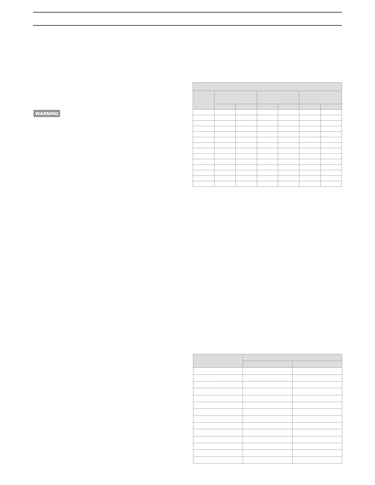
Table 2 - Make-up Air Duct Sizing
When calculating the free area necessary to meet the
make-up air requirements of the enclosure,
consideration must be given to the blockage effects of
louvers, grills and screens.
Screens must have a minimum mesh size of 1/4 in,
6.4 mm. If the free area through a louver or grill is not
known ducts should be sized per Table 2.
Direct Intake Air Option - General
This configuration provides combustion air directly to the
boiler’s air intake using a dedicated pipe when using the
direct vent option. Combustion air can be drawn in
horizontally through an outside wall or vertically through
the roof, see Figures 2, 3, 4 & 5. It must be sized per
Table 3.
Single wall galvanized smoke pipe, single wall aluminum
pipe, flexible aluminum pipe, PVC or CPVC pipe can be
used for the intake air pipe.
Table 3 - Intake Air Pipe Sizing
Required Cross Sectional Duct Area
Input
(MBH)
1/4 in, 6.4 mm
Wire Screen
Metal
Louvers
Wooden
Louvers
in
2
cm
2
in
2
cm
2
in
2
cm
2
0850 212 1368 283 1826 850 5484
1000 250 1613 333 2148 1000 6452
1500 375 2419 500 3226 1500 9677
2000 500 3226 667 4303 2000 12903
2500 635 4031 833 5382 2500 16127
3000 750 4838 1000 6452 3000 19354
3500 875 5645 1167 7522 3500 22581
4000 1000 6452 1334 8592 4000 25808
4500 1125 7257 1500 9678 4500 29031
5000 1250 8065 1666 10748 5000 32258
6000 1500 9676 2000 12904 6000 38708
7000 1750 11290 2334 15044 7000 45162
8000 2000 12904 2668 17184 8000 51616
9000 2250 14514 3000 19356 9000 58062
Model
Size
Pipe Diameter
in mm
0850 6 153
1000 6 153
1500 8 204
2000 8 204
2500 8 204
3000 8 204
3500 10 254
4000 10 254
4500 10 254
5000 12 305
6000 12 305
7000 14 356
8000 14 356
9000 14 356