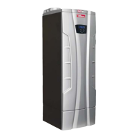
Do you have a question about the RBI Infinity Energy 2 and is the answer not in the manual?
Critical safety guidelines and warnings for proper installation and operation.
Adherence to national and local codes, standards, and regulatory requirements.
Specific installation rules mandated for Massachusetts installations.
Explanation of symbols and indicators used throughout the manual.
Diagram identifying the key components of the burner unit.
Defines the intended applications and operational purposes of the unit.
Specifies the intended use and functions for the IB boiler model.
Specifies the intended use and functions for the IW water heater model.
Details the high efficiency capabilities of the IB boiler.
Guidelines for selecting an appropriate and safe installation site.
Instructions to prevent contaminants from entering the combustion air supply.
Specific considerations for locating an IB boiler installation.
Specific considerations for locating an IW water heater installation.
Precautions and requirements for installing in a residential garage.
Rules and clearances for installation in closets or alcoves.
Minimum distances required around the unit for safe installation and servicing.
Guidelines for clearances from combustible materials.
Requirements and methods for vent and combustion air piping.
Measures to ensure combustion air is free from harmful contaminants.
Guidelines for safely lifting and moving the heater unit.
Step-by-step instructions for physically mounting the heater.
Provides overall dimensions and critical measurements for placement.
Ensuring proper water quality for the IB boiler system to prevent damage.
Procedures for testing and maintaining water quality in the system.
Steps for flushing and cleaning the heating system before installation.
Guidance on analyzing and scheduling water treatment.
Instructions for connecting the supply and return water piping.
Lists and describes components required for near-boiler heating piping.
Details on installing and piping the safety relief valve.
Information on installing expansion tanks and managing makeup water.
Requirements for boiler and central heating pumps.
Piping guidelines for DHW systems with indirect water heaters.
Instructions for connecting hot and cold water supply and return lines.
Details on installing and piping the temperature/pressure relief valve.
Guidance on installing expansion tanks for closed systems.
Requirements for the domestic hot water circulator pump.
Measures to prevent Legionella bacteria growth in the water heater.
Warnings and precautions regarding scalding from hot water.
Specifications for minimum and maximum water flow rates.
Procedures and requirements for safely disposing of condensate.
General overview of electrical connection safety and requirements.
Steps for safely connecting the main power supply cable.
Instructions for wiring the room thermostat to the IB boiler.
Guidance for installing the outdoor sensor on the IB boiler.
Procedure for connecting an analog Vcc input signal.
Instructions for connecting via MODBUS protocol for system integration.
Steps for connecting the IB boiler to an indirect water heater.
Configuration for prioritizing DHW or central heating operation.
Procedure for connecting the IW water heater to a storage tank.
Instructions for installing multiple heaters in a cascade configuration.
Procedure for safely removing a heater from a common venting system.
Definition of Category IV appliances with positive pressure condensing.
Requirements for Category IV venting and air piping systems.
Specifies maximum allowable lengths for combustion and vent piping.
Detailed instructions for installing vent and combustion air piping.
Lists acceptable materials for air inlet piping.
Critical steps for sealing air inlet pipe connections.
Lists acceptable PVC/CPVC materials for vent piping.
Procedure for installing PVC/CPVC vent and air piping correctly.
Specific steps for connecting PVC/CPVC air intake.
Specific steps for connecting PVC/CPVC vent piping.
Lists acceptable stainless steel materials for vent piping.
Procedure for connecting stainless steel air intake.
Procedure for connecting stainless steel vent piping.
Lists acceptable polypropylene materials for vent piping.
Specific steps for connecting polypropylene air intake.
Specific steps for connecting polypropylene vent piping.
Guidelines for single-pipe venting systems without sealed combustion.
Criteria for selecting the optimal location for vent termination.
Instructions for sidewall termination using two-pipe systems.
Criteria for selecting the optimal location for sidewall vent termination.
Steps for preparing wall openings for vent and air pipes.
Guidance on termination methods and required fittings for sidewall systems.
Configuration for terminating multiple sidewall vents and air intakes.
Instructions for sidewall termination using concentric vent systems.
Explanation of the concentric sidewall termination kit.
Steps for installing the concentric sidewall termination.
Instructions for vertical termination using two-pipe systems.
Criteria for selecting the optimal location for vertical vent termination.
Steps for preparing roof openings for vent and air pipes.
Guidance on termination methods and required fittings for vertical systems.
Configuration for terminating multiple vertical vents and air intakes.
Instructions for vertical termination using concentric vent systems.
Explanation of the concentric vertical termination kit.
Criteria for selecting the optimal location for concentric vertical termination.
Steps for installing the concentric vertical termination.
Definition of Category II appliances with negative pressure condensing.
Information on adapters and increasers for Category II systems.
Venting configuration for vertical systems with air from equipment room.
Venting configuration for direct vent systems with rooftop air intake.
Venting configuration for sidewall air intake systems.
Guidelines for common venting of Category II appliances.
Instructions for correctly installing the gas supply piping.
Guidance on sizing natural gas supply piping.
Information and requirements for propane gas installations.
Procedure for checking the inlet gas supply pressure.
Adjustments and considerations for high-altitude operation.
Steps for converting the model 199 between gas types.
Steps for converting models 399-1000 between gas types.
Initial operating procedures and user instructions.
Essential information for users regarding operation and safety.
Procedure for filling the condensate and neutralizing box.
Steps for filling the heating system for IB boilers.
Important safety warnings related to gas supply.
Verification of the heater's gas type setting against the supply.
Step-by-step startup procedures for IB and IW models.
Procedure for testing the ignition control safety shutdown.
Method for checking the gas supply pressure accuracy.
Procedure for checking and adjusting CO2 levels for optimal combustion.
Specific CO2 checking procedure for model 199.
Specific CO2 checking procedure for models 399-1000.
Procedure to verify the unit's gas input capacity.
Understanding the minimum water flow requirement for operation.
Procedure to check and maintain correct water pressure in the system.
Specific steps to check water pressure on IB boilers.
Specific steps to check water pressure on IW water heaters.
Basic steps to initiate the heater's operation.
How to adjust the hot water supply temperature for IW heaters.
Adjusting temperature for indirect water heaters connected to IB boilers.
Adjusting the heating water temperature for IB boilers.
Optimizing efficiency and comfort using outdoor reset.
Understanding built-in delays, alarms, and protective functions.
Measures to protect circulator pumps from seizing.
How the heater prevents freezing during cold conditions.
Configuring the display for energy saving mode.
Accessing and navigating the user menu for basic settings.
Accessing and using the installer menu for diagnostics and adjustments.
Information on diagnostic codes and system status indicators.
Troubleshooting guide for lockout error codes (Loc).
Troubleshooting guide for blocking error codes (Err).
Information on the flue blocked pressure switch safety feature.
Procedure for safely shutting down the heater.
Instructions for cleaning the exterior jacket of the appliance.
Overview of periodic care and maintenance responsibilities.
Procedure for addressing and correcting reported issues.
Safety procedure for checking gas piping for leaks.
Inspection of flue and air lines for integrity and sealing.
Verification of system water pressure and piping integrity.
Procedure for verifying control settings.
Inspection and maintenance of ignition and flame sensors.
Ensuring wiring is in good condition and connections are secure.
Steps to verify the unit's performance after maintenance.
Visual inspection of the burner flame for proper operation.
Procedure for checking the flame signal strength.
Inspection and testing of the safety relief valve.
Checking the area around the heater for contaminants.
Verifying the system pressure gauge reading.
Inspection of the vent piping system for obstructions or damage.
Inspection of the air intake piping system for obstructions or damage.
Inspection of the condensate drain system for leaks.
Checking gas and water piping for leaks.
Procedure for safely shutting down the heater for maintenance.
Testing the low water cutoff safety device.
Steps to safely remove the unit's casing for access.
Procedure for cleaning the burner and heat exchanger.
Ensuring correct positioning of ignition and flame electrodes.
Steps for cleaning the air filter to maintain performance.
Maintenance and cleaning procedures for the condensate trap and box.
Procedure for connecting the display to different burners on multi-burner units.
Instructions for moving or replacing the control board.
Procedure for safely draining water from the heater unit.
Information on water and flue temperature sensors.
Information on the outdoor temperature sensor.
Wiring diagram for the model 199 unit.
Wiring diagrams for models 399 to 1000.
Key to symbols and abbreviations used in electrical diagrams.
Technical specifications and data for the model 199 unit.
List of available spare parts categorized by model number.
Explanation of symbols used in the flow chart.
Accessing and navigating the factory menu for advanced settings.
Flowchart detailing the operational sequence for the boiler.
Flowchart detailing the operational sequence for the water heater.
Details the warranty terms for industrial and commercial units.




 Loading...