SPECTRUM INSTALLATION AND OPERATING INSTRUCTIONS Page 11
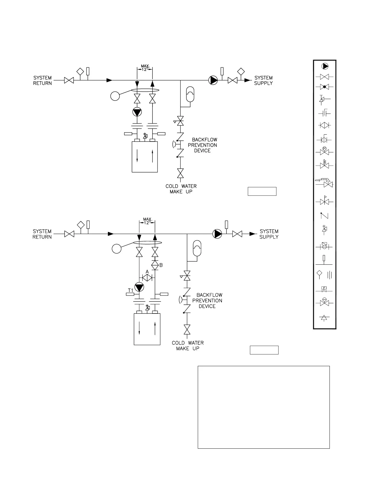
Figure 5 - Typical Primary/Secondary Piping System
(See Notes)
Figure 6 - Low Temperature Piping
(See Notes)
Operated Valve
Air Vent
Pressure Switch
Aquastat Union
Gas Pressure
Regulator
Automatic
Thermometer
Flow Switch
Pressure
Relief Valve
Reducing Valve
Self-Operated
Check Valve
Pressure
Valve
Pump
Motorized Valve
Solenoid
Ball Valve
Bufferfly Valve
Angle Valve
Gate Valve
Globe Valve
Balance Valve
1
1
H-1 Rev 2
H-3 Rev 2
NOTES:
1. Boiler circuit piping must be sized large enough to handle
maximum flow through unit.
2. Boiler pump sized to boiler design flow requirements.
3. All boilers furnished with factory mounted outlet water
temperature gauge.
4. Boiler pump purging required. Use terminals supplied.
Notice: These drawings show suggested piping configuration and
valving. Check with local codes and ordinances for specific requirements.
1. Turn heater on and open valves A & B.
2. After steady-state operation, if T1 is less than Temp-Min
slowly close valve B until T1 climbs to desired operating
temperature above Temp-Min.
3. If T1 is greater than desired operating temperature, slowly
close valve A to adjust to lower desired temperature above
Temp-Min.
4. Check after system operating temperature has
stabilized. Make final adjustments.
5. Follow same adjustment procedure for sealed combustion.
Adjustment Procedure To Maintain Inlet Temperature
Above Dew Point
T1-Temp-Min=110 For Atmospheric
T1-Temp-Min=125
˚
Sealed Combustion
˚
 Loading...