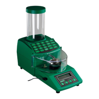
Next, rotate the Cylinder Bushing Assembly counterclockwise to reduce weight or rotate
clockwise to increase weight. If Cylinder Bushing is dicult to rotate loosen Brass Lock
Screw another 1/16th of a turn. When adjustment has been made and desired metered
powder charge is being dispensed, rotate Brass Lock Screw clockwise to secure Metering
Screw in place.
Note: be careful when setting metering screw for light
loads. The Metering Screw can be advanced all the way
in until it contacts the machined bore, when this is done
it needs to be advanced outward slightly, approximately
1/8-1/4 turn, to ensure there is adequate clearance
through entire range of the Metering Cylinder rotation.
When you meter powder, initially after setting up for light
load, you may nd that the Metering Cylinder binds up
and is dicult to rotate. If this happens simple loosen
the Brass Lock Screw and advance Metering Screw out
slightly until Metering Cylinder rotates freely. This will be
the lowest setting you will achieve with this powder type.
When setting up for light loads rotate Metering Cylinder
slightly so it is in the position shown (right). This ensures
the Metering Screw is not advanced passed the bore and
into the powder drop area of the casting.
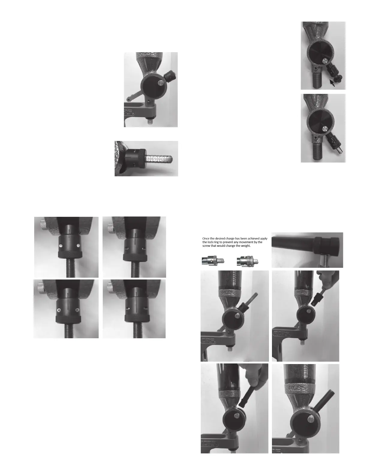
The Metering Screw has a reference scale engraved
on the at portion of the Metering Screw (right). This
allows for recording the setting for a specic powder
type and charge weight being metered. This allows
for quicker setup during the next reloading session.
The Thimble on the Cylinder Bushing Assembly has
four dierent size engraved markings (below), each
marking is 90 degrees apart, to assist in recording
the powder setting. One complete turn of the
Cylinder Bushing will result in .050” of travel of the Metering Screw. Knowing how much the
metered charge will increase or decrease with one complete turn of the Cylinder Bushing will
aid in setting the UPM-3 for desired charge weight. Example: If metering Alliant 300 MP Ball
Powder and the Metering Screw is advanced outward by one rotation of the Cylinder Bushing,
the metered charge will increase by approximately 4.5 grains.
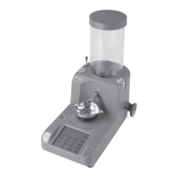
Before using UPM-3 to reload actual cartridges, we need to condition the Powder Measure,
to do this, set the powder measure for the maximum charge by rotating the Cylinder Bushing
Assembly clockwise, this will advance the metering screw outward until it reaches the end of
its travel. Fill the Hopper with powder and cycle UPM-3 until all powder has been metered and
dispensed. The UPM-3 holds approximately 1/2 pound of powder, so do this twice so a total of
one pound of powder has been metered through the Powder Measure. Doing this will deposit
a thin lm of graphite on the internal features allowing the powder to ow more evenly and
smoothly resulting in more consistent metered charges.
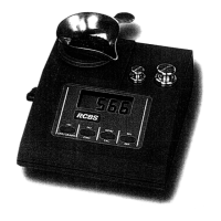
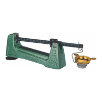
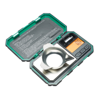
Checking the weight of the dispensed volumetric charge is very important and needs to be
done every time the UPM-3 is set up and used. This should also be done if the reloading session
is stopped and started at a later time. This can be done by weighing the dispensed volumetric
charge on either an electronic or mechanical scale.
Once the powder measure has been set, place the Screw Lock Ring, from Bag 3, onto the
Metering Screw and rotate clockwise until it makes contact with the Cylinder Bushing Assembly,
acting as a jam nut preventing any unwanted rotation of the Cylinder Bushing Assembly and
preventing any unwanted movement of Metering Screw. If the amount of powder being
dispensed needs to be adjusted, you will need to loosen the Screw Lock Ring prior to adjusting,
as shown in Figure A. Once the desired amount of powder dispensed is achieved re-tighten
the Screw Lock Ring as shown in Figure B. Cycle the UPM at least ten times and the weight
conrmed using an electronic or mechanical scale. This is done
to ensure the cycling of the handle is consistent and dispensing
the metered charge accurately. If cycling of the handle is
inconsistent, there will be a variance in the dispensed charge
weight. Be sure to use the same uniform movements for each
metered charge. Depending upon handle orientation, raise or
lower the handle smoothly to the end of its rotation; this is the
ll position where the powder from hopper will ll the Metering
Cylinder. Leave the cylinder in this position briey to ensure
the Metering Cylinder is lled completely, especially for larger
dispense weights. If operation is too fast the cylinder may not
ll completely resulting in a lower than desired charge weight.
Lower or raise the handle smoothly to the end of its rotation
to dispense the metered powder charge. Provide a slight tap of
the handle to ensure all metered powder has been dispensed.
This is one technique, there are others that work just as well.
Use whichever technique works best for you and provides the
best results.
Powder type will inuence the accuracy of dispensed charges.
For example, Ball and Flake type powders will meter much
better and yield better accuracies than that of Extruded type
powders. If Extruded type powders are preferred, many powder
manufactures produce short cut Extruded powders which
meter much better in volumetric powder measures.
Powder should not be left in the Powder Measure for long
periods of time as it will deteriorate and may clog and jam the
Metering Cylinder it will also etch the Powder Hopper. By using the Drain Tube Attachment,
powder can be removed without removing the Powder Measure from stand. Ensure the
Metering Cylinder is rotated so that it is in the dispense position. Remove or loosen the Brass
Lock Screw to remove the Metering Screw assembly from the Cylinder. Insert the Drain Tube
attachment into the Metering Cylinder and install the Brass Lock Screw. Make sure the relief
on the Drain Tube attachment is positioned in line with the lock screw hole so the Lock Screw
will secure the Drain Tube in place. Rotate handle lowering the Drain Tube and empty powder
from Powder Measure. Make sure you have a container large enough to collect all powder
from hopper and position in front of Drain Tube while lowering as powder will begin owing
as soon as Drain Tube is lowered. When powder hopper has been emptied, the Hopper can be
removed, and any residual powder can be removed from powder measure.
Cylinder position when setting
for lightest load
Relief on Drain Tube
Dispense Position
Remove Metering
Screw Assembly
Inserting
Drain Tube
Attachment
Drain Tube
Attachment
Installed
Engraved Markings on Thimble
SETTING 2SETTING 1
SETTING 4SETTING 3
Reference Scale on Metering Screw
4
FIG. B
FIG. A
Next, rotate the Cylinder Bushing Assembly counterclockwise to reduce weight or rotate
clockwise to increase weight. If Cylinder Bushing is dicult to rotate loosen Brass Lock
Screw another 1/16th of a turn. When adjustment has been made and desired metered
powder charge is being dispensed, rotate Brass Lock Screw clockwise to secure Metering
Screw in place.
Note: be careful when setting metering screw for light
loads. The Metering Screw can be advanced all the way
in until it contacts the machined bore, when this is done
it needs to be advanced outward slightly, approximately
1/8-1/4 turn, to ensure there is adequate clearance
through entire range of the Metering Cylinder rotation.
When you meter powder, initially after setting up for light
load, you may nd that the Metering Cylinder binds up
and is dicult to rotate. If this happens simple loosen
the Brass Lock Screw and advance Metering Screw out
slightly until Metering Cylinder rotates freely. This will be
the lowest setting you will achieve with this powder type.
When setting up for light loads rotate Metering Cylinder
slightly so it is in the position shown (right). This ensures
the Metering Screw is not advanced passed the bore and
into the powder drop area of the casting.
The Metering Screw has a reference scale engraved
on the at portion of the Metering Screw (right). This
allows for recording the setting for a specic powder
type and charge weight being metered. This allows
for quicker setup during the next reloading session.
The Thimble on the Cylinder Bushing Assembly has
four dierent size engraved markings (below), each
marking is 90 degrees apart, to assist in recording
the powder setting. One complete turn of the
Cylinder Bushing will result in .050” of travel of the Metering Screw. Knowing how much the
metered charge will increase or decrease with one complete turn of the Cylinder Bushing will
aid in setting the UPM-3 for desired charge weight. Example: If metering Alliant 300 MP Ball
Powder and the Metering Screw is advanced outward by one rotation of the Cylinder Bushing,
the metered charge will increase by approximately 4.5 grains.
Before using UPM-3 to reload actual cartridges, we need to condition the Powder Measure,
to do this, set the powder measure for the maximum charge by rotating the Cylinder Bushing
Assembly clockwise, this will advance the metering screw outward until it reaches the end of
its travel. Fill the Hopper with powder and cycle UPM-3 until all powder has been metered and
dispensed. The UPM-3 holds approximately 1/2 pound of powder, so do this twice so a total of
one pound of powder has been metered through the Powder Measure. Doing this will deposit
a thin lm of graphite on the internal features allowing the powder to ow more evenly and
smoothly resulting in more consistent metered charges.
Checking the weight of the dispensed volumetric charge is very important and needs to be
done every time the UPM-3 is set up and used. This should also be done if the reloading session
is stopped and started at a later time. This can be done by weighing the dispensed volumetric
charge on either an electronic or mechanical scale.
Once the powder measure has been set, place the Screw Lock Ring, from Bag 3, onto the
Metering Screw and rotate clockwise until it makes contact with the Cylinder Bushing Assembly,
acting as a jam nut preventing any unwanted rotation of the Cylinder Bushing Assembly and
preventing any unwanted movement of Metering Screw. If the amount of powder being
dispensed needs to be adjusted, you will need to loosen the Screw Lock Ring prior to adjusting,
as shown in Figure A. Once the desired amount of powder dispensed is achieved re-tighten
the Screw Lock Ring as shown in Figure B. Cycle the UPM at least ten times and the weight
conrmed using an electronic or mechanical scale. This is done
to ensure the cycling of the handle is consistent and dispensing
the metered charge accurately. If cycling of the handle is
inconsistent, there will be a variance in the dispensed charge
weight. Be sure to use the same uniform movements for each
metered charge. Depending upon handle orientation, raise or
lower the handle smoothly to the end of its rotation; this is the
ll position where the powder from hopper will ll the Metering
Cylinder. Leave the cylinder in this position briey to ensure
the Metering Cylinder is lled completely, especially for larger
dispense weights. If operation is too fast the cylinder may not
ll completely resulting in a lower than desired charge weight.
Lower or raise the handle smoothly to the end of its rotation
to dispense the metered powder charge. Provide a slight tap of
the handle to ensure all metered powder has been dispensed.
This is one technique, there are others that work just as well.
Use whichever technique works best for you and provides the
best results.
Powder type will inuence the accuracy of dispensed charges.
For example, Ball and Flake type powders will meter much
better and yield better accuracies than that of Extruded type
powders. If Extruded type powders are preferred, many powder
manufactures produce short cut Extruded powders which
meter much better in volumetric powder measures.
Powder should not be left in the Powder Measure for long
periods of time as it will deteriorate and may clog and jam the
Metering Cylinder it will also etch the Powder Hopper. By using the Drain Tube Attachment,
powder can be removed without removing the Powder Measure from stand. Ensure the
Metering Cylinder is rotated so that it is in the dispense position. Remove or loosen the Brass
Lock Screw to remove the Metering Screw assembly from the Cylinder. Insert the Drain Tube
attachment into the Metering Cylinder and install the Brass Lock Screw. Make sure the relief
on the Drain Tube attachment is positioned in line with the lock screw hole so the Lock Screw
will secure the Drain Tube in place. Rotate handle lowering the Drain Tube and empty powder
from Powder Measure. Make sure you have a container large enough to collect all powder
from hopper and position in front of Drain Tube while lowering as powder will begin owing
as soon as Drain Tube is lowered. When powder hopper has been emptied, the Hopper can be
removed, and any residual powder can be removed from powder measure.
Cylinder position when setting
for lightest load
Relief on Drain Tube
Dispense Position
Remove Metering
Screw Assembly
Inserting
Drain Tube
Attachment
Drain Tube
Attachment
Installed
Engraved Markings on Thimble
SETTING 2SETTING 1
SETTING 4SETTING 3
Reference Scale on Metering Screw
4
FIG. B
FIG. A
 Loading...