Specifications
MECHANICAL (
Including 1/4” [6.4mm] mounting bracket)
:
8310 Lock Dimensions:
1 5/8”D x 2 7/8”W x 10 1/2”L (41mm x 73mm x 268mm)
8320 Lock Dimensions:
1 5/8”D x 2 7/8”W x 21”L (41mm x 73mm x 533mm)
8330 Lock Dimensions:
1 5/8”D x 2 7/8”W x 34 1/2”L (41mm x 73mm x 876mm)
8340 Lock Dimensions:
1 5/8”D x 2 7/8”W x 46 1/2”L (41mm x 73mm x 1181mm)
NOTE: Both 8330 and 8340 housings may be cut to length on site
Standard Armature plate dimensions:
5/8”D x 2 3/8”W x 7 7/16”L (16mm x 60mm x 189mm)
DSS Armature plate is 10”L (254mm)
ELECTRICAL:
V
oltage:
12VDC or 24VDC
(Selected by choosing appropriate wiring terminals)
Cur
rent:
0.28A @ 12VDC
0.28A @ 24VDC
NOTE: 8320 lock contains 2 control boards
that will each draw 0.28A
SCS Output Relay: SPDT relay. Contacts rated at 1.25A@24VDC
DSS Reed Switch: Magnetically actuated SPDT switch.
Contacts rated for 0.20A @12VDC and 0.12A @ 24VDC
ENVIRONMENTAL: Not for use in outdoor environments.
Circuit board operating temperature: -14 to 140˚F (-10 to 60˚C)
NOTE: Specifications may change without notice.
8300 Series Troubleshooting Guide
Problem Solution
Remove anti-tamper screw and cavity screw. Insert supplied Allen wrench into
mounting bolt holes in the bottom of the lock housing and turn. (See Fig.3)
- Check power supply. DC power should be slightly over the voltage
specifications outlined on the packaging. eg: for 12VDC operation
supply should be set at 12VDC-13VDC.
-
Check connections at power supply
, connected r
eleasing devices, lock
ter
minals and lock cir
cuit board to magnet core.
- Check delayed relock wiring and time setting
-
Check that the momentar
y switch does not include a shunted light option
Check to see that armature plate is correctly aligned with the
electromagnetic lock. If there is improper alignment, make a 1/4” turn of the
armature plate mounting bolt and check for alignment.
CAUTION: The
armature plate must remain affixed securely to the door or serious bodily
injury or property damage may occur. Bolt should be tight enough to hold
the armature plate to the door while still allowing for alignment with the
electromagnetic lock.
This generally indicates that the lock is either operating on AC voltage or there
is some AC voltage present in the DC supply. A properly filtered and regulated
DC power supply is required to achieve optimal operation from the lock.
Ensur
e that switching devices ar
e inter
r
upting the DC power and not the
AC power supply voltage.
Ensure rubber washer on armature plate mounting bolt has not been
r
emoved or damaged
- Check that switching device interrupts the positive wire and not the
negative wir
e (See Fig. 2)
-
Remove any Diodes or other suppr
ession devices that may be installed
Cannot remove the lock mounting bracket from top of
magnet for installation.
Lock is installed but has no holding force at all.
Lock has enough holding force to lightly hold a
screwdriver or set of pliers but door will not lock.
Lock is operating and locking but the armature plate is
“humming” against the surface of the lock.
Lock is not releasing immediately upon removal of power
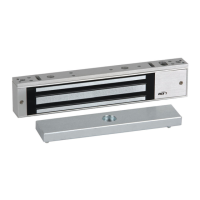
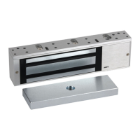
8310, 8320, 8330 & 8340 Electromagnetic Lock
Installation Instructions (Continued)
4
NOTE: All RCI electromagnetic locks must be powered with filtered and regulated DC power supplies such as the RCI 10 Series UL
Listed power supply. RCI offers a full line of power supplies and switching devices that are suitable for use with the 8300 Series locks.
Voltage 8310 8320 8330 8340
12VDC 0.28A 0.28A x 2= 0.56A 0.28A 0.28A
24VDC 0.28A 0.28A x 2= 0.56A 0.28A 0.28A
Power Supply
 Loading...