EasyManua.ls Logo

RCI 8310 User Manual

RCI 8310
8 pages
To Next Page IconTo Next Page
Page #1 background imageLoading...
Page #1 background image
©2007 RUTHERFORD CONTROLS INT’L CORP. WWW.RUTHERFORDCONTROLS.COM
U
SA: 2
69
7 INTERNATIONAL PARKWAY, PKWY 5, VIRGINIA BEACH, VA 23452 • CANADA: 210 SHEARSON CRESCENT, CAMBRIDGE, ON N1T 1J6
P
HON
E • 1.800.2
65.663
0 • 5
19.621.7651 • FAX: 1.800.482.9795 • 519.621.7939 • E-MAIL: SALES@RUTHERFORDCONTROLS.COM
INSTALLATION
8310/8320
8330/8340
Electromagnetic Locks
Pre-Installation Instructions
1. This product must be installed according to all applicable
building and life safety codes.
2. Due to the variety of mounting configurations available with
this product, a survey and assessment of the physical area
in which the pr
oduct will be installed must be performed.
3. The door frame must be inspected and deemed structurally
sound prior to installation of the electromagnetic lock. The
structural integrity of the mounting surfaces must be strong
enough to meet or exceed the holding force of the product.
4. The product must be protected from potential damage due
to intruders or tampering.
5. The product should be installed in a location that will not
hinder or create a potential safety hazard to authorized
personnel accessing the protected area.
6. Because electromagnetic locks are used in a variety of
applications and different door frame configurations, an
experienced installer with knowledge of this product must
make a determination of the optimal mounting method for
this specific application.
7. The components, hardware, installation instructions and
mounting template included with this product are intended
for use on outswinging doors.
8. Do not install this product on the exterior of buildings.
9. Separate accessories not included with this pr
oduct must be
used in the following applications:
Inswinging doors
Narrow head jamb situations or center-hung doors
Wherever there is insufficient space on the door frame
header to mount the lock
Glass or Herculite doors that do not have a door frame
Hollow metal or wood frames where the door stop is
not thick enough to allow the product to be installed
Wherever an obstruction in the door prevents
installation of the armature plate at a proper height
Doors that do not permit the armature plate to be
mounted low enough to meet the magnet surface
Refer to the Product Accessories Guide section of the
Installation Instructions for further information.
10. Installation of this product should be done by an
experienced installer with knowledge of this product.
NOTE: It is highly recommended that thread locking compound
be applied to all screws during installation to reduce chance of
screws loosening over extended time.
®
IS8310-40
PCN070022-B
P11/07DA
1. Mount the electromagnetic lock to the door frame as outlined
on the installation template included with the product.
NOTE: During installation of the armature plate to the door it is
essential that the ar
matur
e plate remains movable. The armature
plate must be allowed to pivot on the center-mounting bolt to
allow pr
oper alignment with the magnet sur
face. If the plate is
not aligned with the magnet sur
face, the lock may lose holding
force or not lock at all.
The head of the armature mounting bolt ships with a rubber
washer af
fixed to it. This washer should pr
oject slightly beyond
the surface of the armature plate. This is to allow the washer to
expand when power is removed and break the air vacuum
between the plate and the magnet sur
face. If this washer is
removed or trimmed the lock will appear to have some holding
force even when power is removed.
For added safety, thread locking compound has been provided for
the armature plate bolt and the four captive electromagnetic lock
mounting scr
ews.
WARNING: Improper installation, maintenance, inspection or
usage of the product or any related accessories or parts may cause
the electromagnetic lock, armature plate and associated hardware
to disengage and fall, causing serious bodily injury and property
damage. Ruther
for
d Contr
ols Int'l Corp. will not be liable to the
installer
, pur
chaser
, end user or anyone else for damage or injur
y
to person or pr
oper
ty due to improper installation, care, storage,
handling, maintenance, inspection, abuse, misuse or act of God or
natur
e involving this pr
oduct or any related accessories or parts.
2. Route the power supply connecting wire through the door
frame and into the wire access hole in the top of the magnet
housing. Connecting wir
e should be of suf
ficient gauge for
the lock being installed and the distance being run. See table
for current draw specifications and wiring gauge chart.
Installation Instructions
PLEASE DELIVER ALL INSTALLATION INSTRUCTIONS TO
THE END-USER UPON COMPLETION OF THE INSTALLATION.

Other manuals for RCI 8310

Question and Answer IconNeed help?

Do you have a question about the RCI 8310 and is the answer not in the manual?

RCI 8310 Specifications

General IconGeneral
BrandRCI
Model8310
CategoryLocks
LanguageEnglish

Summary

Pre-Installation Instructions

Compliance with Codes

Ensure installation adheres to all applicable building and life safety codes.

Site Assessment

Conduct a survey and assessment of the physical installation area due to varied mounting configurations.

Structural Integrity Check

Inspect the door frame for structural soundness before lock installation.

Damage Protection

Ensure the product is protected from potential damage due to intruders or tampering.

Safe Location

Install the product in a location that does not hinder access or create safety hazards.

Mounting Method Selection

An experienced installer must determine the optimal mounting method for the specific application.

Outswinging Door Components

Included components are intended for use on outswinging doors.

Exterior Installation Prohibition

This product must not be installed on the exterior of buildings.

Accessory Applications

Details specific applications requiring separate accessories for installation.

Installer Qualification

Installation should only be performed by an experienced installer knowledgeable about the product.

Installation Instructions

Lock Mounting

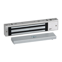
Mount the electromagnetic lock to the door frame as outlined on the installation template.

Wire Routing

Route the power supply connecting wire through the door frame and into the wire access hole.

Lock Assembly

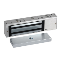
Details about the physical assembly of the lock housing and mounting screws.

Lock Options

Explains remote indication features like SCS and DSS for status monitoring.

Inspection and Maintenance

Guidelines for regular checks and upkeep of the lock and its components.

Wiring and Features

Power Connections

Illustrates and explains how to connect the DC power source to the lock terminals.

Delayed Relock Feature

Describes the built-in delayed relock feature and its adjustment via potentiometer.

Optional SCS and DSS Wiring

Details wiring for optional Security Condition Sensor and Door Status Sensor features.

Technical Specifications

Mechanical Dimensions

Provides detailed mechanical dimensions for various lock models (8310-8340).

Electrical Requirements

Specifies voltage, current draw, and relay ratings for the electromagnetic locks.

Environmental Conditions

Outlines operating temperature range and restrictions for outdoor use.

Troubleshooting Guide

Lists common problems and their solutions for installation and operation.

Product Accessories Guide

Brackets for Mounting

Details Top Jamb, Angle, and 'L' brackets for various frame mounting scenarios.

Glass Door Mounting

Describes the Glass Door Bracket for mounting armature plates on glass doors.

Mounting Aids

Explains Split Armature Plates, Filler Bars, and Spacer Bars for specific mounting needs.

Armature Holder

Details the Armature Holder for mounting armature plates in challenging door configurations.

Optional Kits and Switches

Lists available DSS Retrofit Kit, Cover Tamper Switch, and Cover Security Screw.

Wire Gauge Selections

Wire Gauge Chart @24V

Table showing recommended wire gauge based on load current and wire run length at 24V.

Wire Gauge Chart @12V

Table showing recommended wire gauge based on load current and wire run length at 12V.

Related product manuals