DCN 140-02165-01 4/20/12 11
HVAC SYSTEM QUICK TEST
In the event that you have difficulty with the TR65 controlling the HVAC system, you can perform the
following quick test to confirm that the HVAC system is working correctly.
The TR65 HVAC Control Unit connects to the HVAC system at the normal thermostat connections on
the HVAC unit. Standard thermostat control of the HVAC systems consist of contact closures in the
thermostat. You can verify that your HVAC system is working correctly by duplicating these contact
closures by shorting across the proper terminals on the HVAC systems thermostat connection. Refer to
the following HVAC system example.
HVAC SYSTEM EXAMPLE
For Standard HVAC systems:
Go to the HVAC system’s thermostat connection terminals
Verify FAN operation by shorting across the R to G (Fan) terminals
HVAC system fan should come on. (Caution: Delays may be
part of normal start up cycle, check HVAC system’s manual)
If not check HVAC system power and fuses.
If power is OK, HVAC system is NOT working correctly.
Verify HEAT operation by shorting across R to W (Heat) terminals (A Fan call is not necessary for gas furnaces)
Heating operation should start. (Caution: Delays may be part of normal start up cycle, check HVAC
System’s manual)
If not, check wiring, check 24VAC power is on R terminal. (measured across R to C).
If power is OK, HVAC system is NOT working correctly.
Verify COOL operation by shorting across R to Y (Compressor) and R to G (Fan) terminals
Cooling operation should start. (Caution: Short Cycle Protection 5 minute delays are normal
between calls and may delay start)
If not, check wiring, check 24VAC power is on R terminal (measured across R to C)
If power is OK, HVAC system is NOT working correctly.
If any of these checks fail, the HVAC system is not working correctly. Call an HVAC professional.
Heat Pump Systems are similar, but have an additional output for the changeover valve.
The basic fan and heating test are the same.
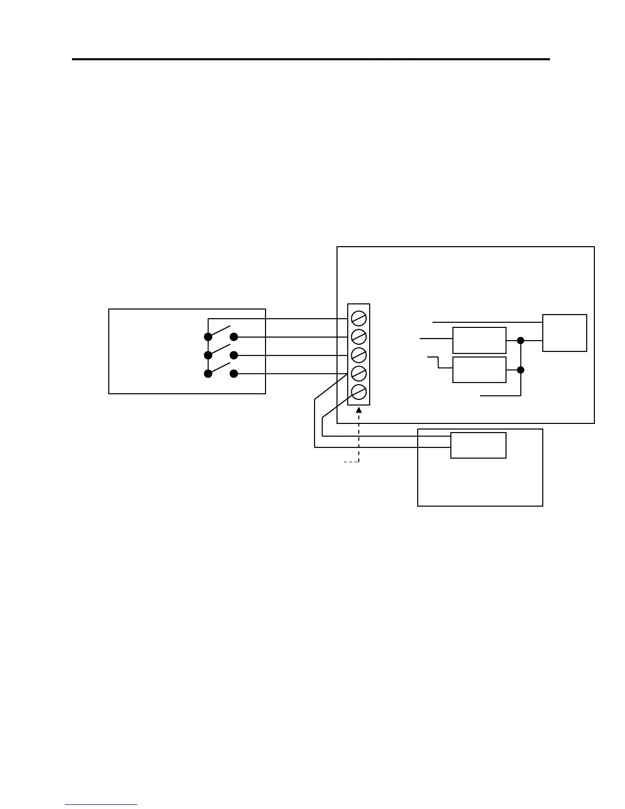
HVAC SYSTEM
STANDARD GAS/AC
This is a simplified diagram of a Standard HVAC
System and Thermostat. The Thermostat operates
like switches to control the HVAC Fan, Heat, and Cool
functions.
 Loading...