Re S.p.A. US3
Rev.12/04/11 22/23
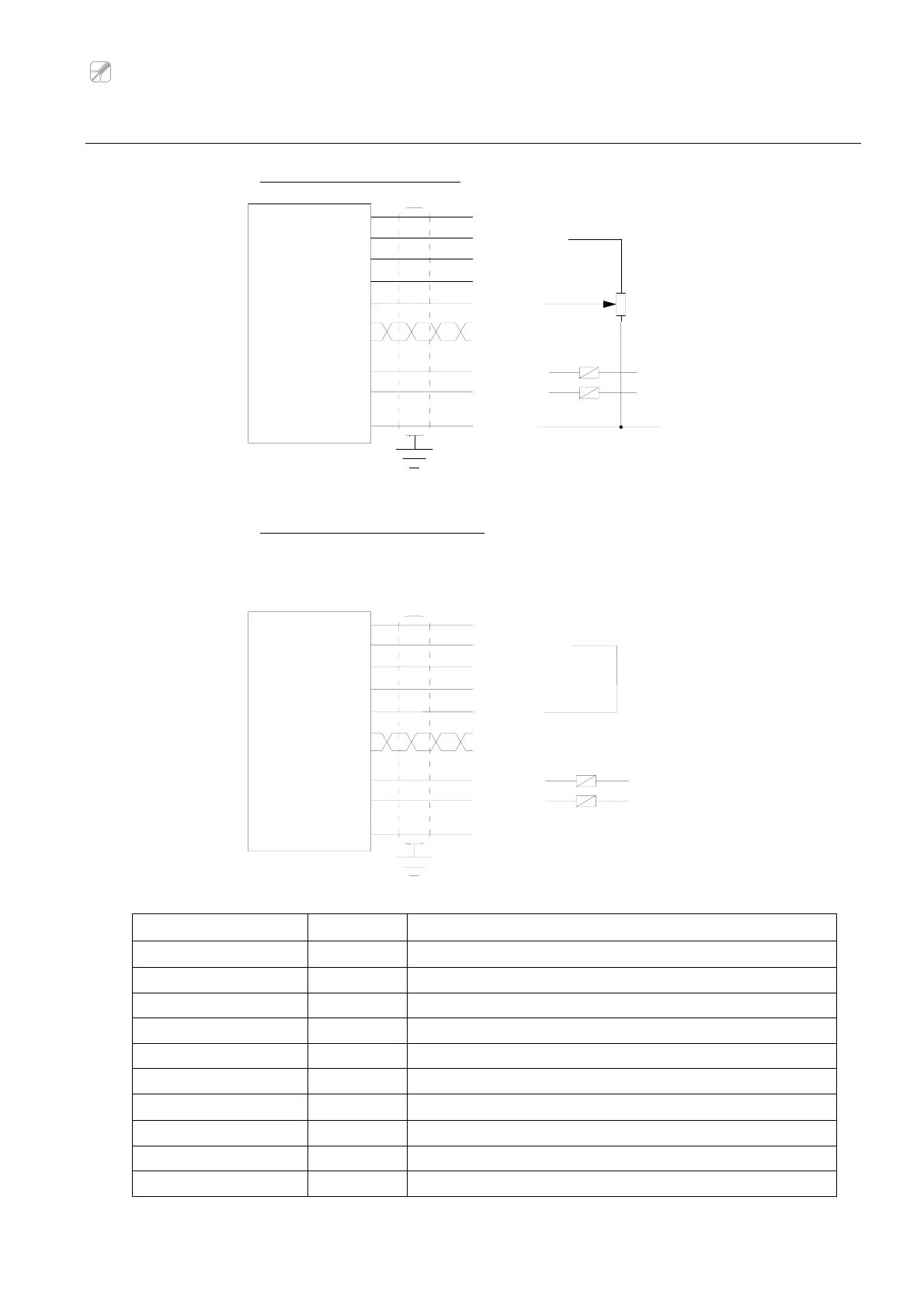
Electrical connection diagrams
Configuration with setpoint potentiometer (see on page 19)
Configuration without setpoint potentiometer:
In this case it’s necessary to link up the green cable to the brown one; if you do not link the cables the
regulated analog output (blue wire) is constant and 0Volt (or 4mA).
Wire colour Pin Function
Red 1
Supply 18÷30Vdc
Black 8 0V
White 9 Alarm output 1
Yellow 10 Alarm output 2
Orange 4 Proportional analog output
Blue 3 Regulated analog output
Green 6
Setpoint input 0÷10V
Brown 5 Setpoint reference +10Vdc
Grey 7 RS485 serial output - (B)
Violet 2 RS485 serial output + (A)
Setpoint potentiometer
GREEN
SETPOINT IN
ALARM 2 OUT
0 V
ALARM 1 OUT
RS485 - (B)
RS485 + (A)
YELLOW
Vrelay
BLACK
Coil relay
Coil relay
WHITE
GREY
VIOLET
Vrelay
REG. OUT
PROP. OUT
Vref
+VDC
BLUE
ORANGE
BROWN
RED
PROP. OUT
ORANGE
ALARM 1 OUT
ALARM 2 OUT
0 V
SETPOINT IN
RS485 + (A)
RS485 - (B)
REG. OUT
Coil relay
Coil relay
BLACK
WHITE
YELLOW
Vrelay
Vrelay
GREEN
VIOLET
GREY
BLUE
+VDC
Vref
RED
BROWN
(≥ 10KΩ)