INSTALLATION
As
with
other quality sound equipment, adequate ventilation
will
extend the
trouble-free life
of
your Audio Power Meter. You should
not
install this
unit
in the
area confined
with
other heat generating equipment.
Connect the line cord
to
a standard 120V160Hz (or
240V
150Hz
for
Aust-
ralian
Models)
AC Outlet. The power consumption is 7 Watts. You may
want
to
connect
to
the switched outlet
of
your Amplifier IReceiver so
that
you
can
turn
the
unit
"on"
and
"off"
with
your system's main
power
switch.
CONNECTION
1.
Disconnect power
from
your Amplifier/Receiver.
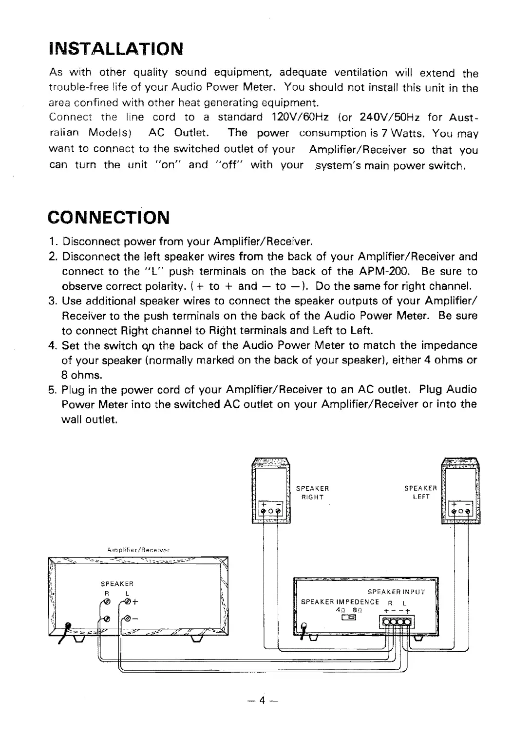
2.
Disconnect
the
left speaker wires from the back
of
your Amplifier/Receiver and
connect
to
the
"l"
push terminals on the back
of
the APM-200.
Be
sure
to
observe correct polarity.
(+
to
+ and -
to
-).
Do the same
for
right channel.
3.
Use additional speaker wires
to
connect the speaker
outputs
of
your
Amplifier/
Receiver
to
the push terminals on the back
of
the
Audio
Power Meter.
Be
sure
to
connect Right channel
to
Right terminals and Left
to
Left.
4.
Set the switch qn the back
of
the
Audio
Power
Meter
to
match the impedance
of
your
speaker (normally marked on the back
of
your
speaker), either 4 ohms
or
Bohrns.
5.
Plug in the
power
cord
of
your Amplifier/Receiver
to
an
AC
outlet. Plug
Audio
Power Meter into the switched
AC
outlet on your Amplifier/Receiver
or
into the
wall outlet,
IJ"!;""':.~'
"",,!,".-"!,,-'
-
I'i:
...
~
:
:
SPEAKER
SPEAKER
l
\
,
:g:
RIGHT
LEFT
:I~I~
.
~
Ii
.
.--
'-
Am
pilile
rlRece:ver
r\l..
-
-'-'
.-~",,-
--..--.."
...
::;-:::.
--;..-~-~
-~;::
,-
fl
,
,
SPEAKER
:;
"~
R L
\
SPEAKER
INPUT
,I.
,:,
(0
...-0+
~\
SPEAKER
IMPEDENCE
R L
\
,
4>2
en
+
--;-
),
.\
~
!~
:1
c::::§]
I
~
r"
II
\'
.
l!
I
~
"""-
'"
""""
1""
I
....
-::::;;;
~~
--~~
!
..
r
\J
I
\J
I
'\..1
\..I
I
-4-
 Loading...