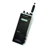
Do you have a question about the Realistic PRO-2026 and is the answer not in the manual?
Detailed technical specifications including band coverage, frequency range, display, and controls.
Conditions under which specifications are measured, including power, frequency, and signal levels.
Procedure to adjust the Phase-Locked Loop for frequency accuracy.
Procedure to adjust the Voltage-Controlled Oscillator for frequency stability.
Procedure to adjust the discriminator circuit for accurate demodulation.
Procedure to align the Intermediate Frequency amplifier stages.
Procedure to align receiver sensitivity and performance.
Procedure to adjust the squelch circuit for noise muting.
Flowchart for diagnosing reception issues.
Flowchart for diagnosing audio output problems.
Flowchart for diagnosing RF signal path issues.
Top view layout of the main printed circuit board components.
Top view layout of the control printed circuit board components.
Bottom view layout of the control printed circuit board components.
Bottom view and chip placement for the main PCB.
Top view wiring details for the main PCB.
List of electrical components for the main PCB.
List of electrical components for the control PCB.
List of physical parts with reference numbers.
Chart showing expected voltages for ICs and transistors.
Diagrams showing lead identification for semiconductors.
Schematic diagram for the control section.
Schematic diagram for the main section.
Internal diagrams for key ICs.
Internal diagrams for other key ICs.