Do you have a question about the Realistic Pro-53 and is the answer not in the manual?
Details specific components like transistors, ICs, and switches on the schematic.
Details the number of transistors, integrated circuits, and diodes used.
Specifies the operational frequency bands for the receiver.
Details the VHF frequency ranges for maximum sensitivity.
States the minimum signal level for clear reception.
Defines the receiver's ability to reject adjacent frequencies.
Quantifies rejection of signals on nearby frequencies.
Specifies rejection of unwanted signals at the image frequency.
Defines how fast the receiver scans through channels.
Describes the time delay before resuming scan after a signal.
Lists the Intermediate Frequencies used in the receiver.
Identifies the types of filters used for signal processing.
Defines the threshold for the squelch circuit.
Specifies the output power of the audio amplifier.
Details the type of crystals required for operation.
Specifies the voltage, frequency, and power consumption.
Instructions for connecting the receiver to AC power and an antenna.
Guidance on inserting crystals and setting program switches for reception.
Warnings about handling internal components and using specific crystals.
Description of the power switch and volume adjustment.
Explains the function of the squelch control for noise reduction.
Details the function of the switch for SCAN, STOP, and MANUAL modes.
Explains how to activate or lock out channels.
Describes the LEDs that indicate active channels.
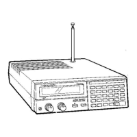
Details the Headphone Jack, Telescopic Antenna, and Antenna Jack.
Procedure for turning on the receiver and setting the squelch.
Instructions for continuous scanning, manual scanning, and locking out channels.
Explanation of features that skip locked channels and delay scan resumption.
Information about recommended accessories like headphones.
Guidance on selecting optimal frequencies for best reception.
Lists various services and signals that can be monitored.
Tips for obtaining frequency information from local sources.
Instructions for monitoring National Weather Service broadcasts.
General advice on maintaining the electronic unit.
| Bands | VHF, UHF |
|---|---|
| Antenna | Telescopic |
| Type | Scanner |
| Frequency Range | 406-512 MHz |
| Mode | FM |
| Power Supply | 9V |