-
REC Installation Manual - Module REC Alpha - IEC61215/IEC61730
Ref: PM-IM-23
REC Installation Manual - Module REC Alpha - IEC61215/IEC61730
Ref: PM-IM-23
Rev: . US
REC Installation Manual - Module REC Alpha - IEC/IEC
Ref: PM-IM-
Rev: . US
-
NOTE
In areas of snow build-up, panels can be subjected to forces in excess of the stated limit even when snow depth does
not appear extreme, potentially causing damage to the panel. If the installation may be affected by this, further panel
support is recommended, especially on the lower row of panels. In the case of any questions regarding mounting
systems, or if the mounting system to be used does not match any of the instructions shown in this installation
manual, please contact REC for further support.
MOUNTING METHODS: SLIDE IN SYSTEMS
When installing using slide in systems the mounting system must meet the same specifications including grip lengths, depths and spacing
as specified for clamping and the mounting system must be able to withstand the correct load pressures.
When installing solar panels using a slide-in system, the drainage holes found in the underside of the panel frame (Fig. ) must not be covered.
For any questions regarding installation on such systems, please contact REC directly.
MOUNTING METHODS: MOUNTING HOLES
The REC solar panels covered by this manual can be installed utilizing the four mounting holes (. x . in / x . mm) on the underside
of the panel (Fig. ). Installation must be performed in conjunction with a device, e.g., screws or lockbolts, with specifications suitable for
the installation (Fig. ).
CAUTION
The product warranty will be voided if additional holes are made in the frame. All fixing and fastening materials
must be corrosion resistant.
Installing REC Alpha solar panels using the mounting holes has been found to comply with IEC & IEC requirements for down-
ward pressure,e.g., snow, of up to Pa ( Pa design load*) and upward pressure,e.g., wind, of up to Pa ( Pa design load*)
according to the following instructions (*design loads apply a safety factor of . to the stated test load, e.g., test load Pa / . =
Pa design load).
When installing using mounting holes, the frame and panel edge of each panel must be supported by two rails of aluminium or galvanized
steel suitable for the application and appropriate for the local environment. Observe the following procedures when using mounting
holes:
• The mounting construction must be of a corrosion resistant material, e.g., aluminum or galvanized steel, and appropriate for
the local environment,
• All four mounting holes in the frame must be used (Fig. ),
• A washer must be used between frame and rail,
• Additional electrical bonding to Ground is required for the support structure,
• REC modules must be secured with a torque between - Nm (- lbf/in). Refer to the fixing device manufacturer’s
installation instructions for preload or torque values.
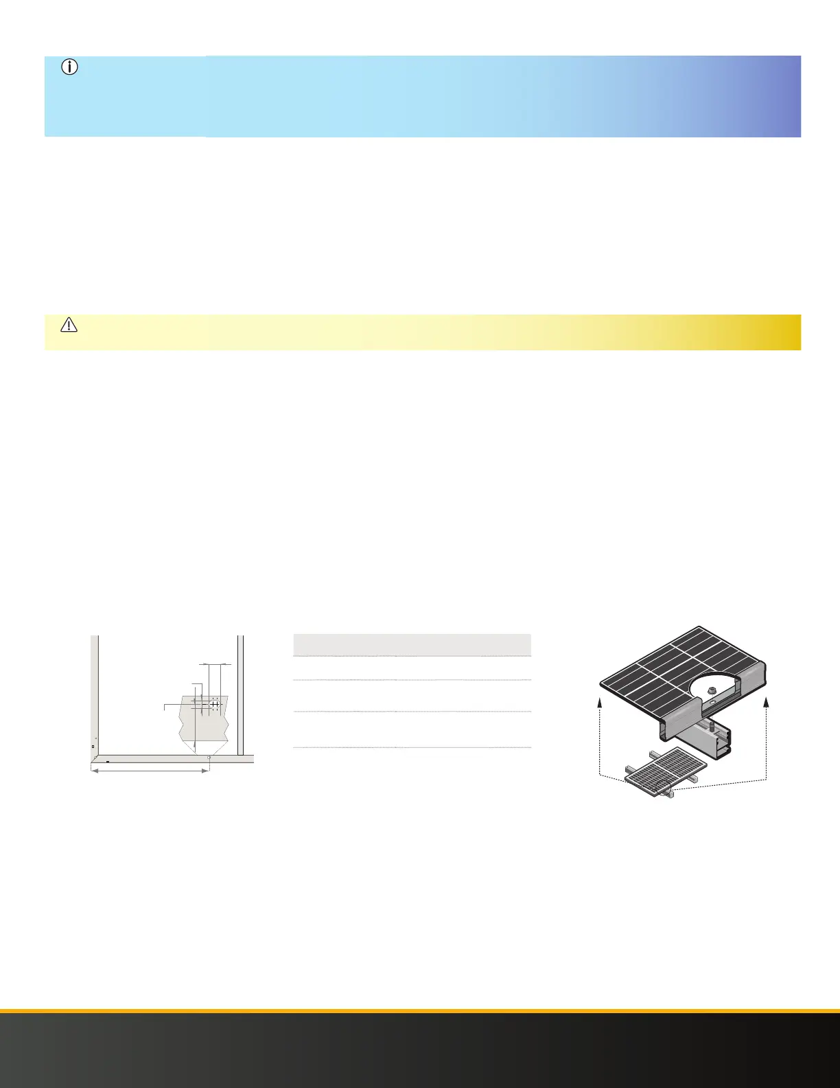
Fig. Mounting hole installation example
11 mm ±0.2
[0.43 in ±0.8]
6.6 mm
±0.2
[0.26 in ±0.08]
20.5 mm
±0.5
[0.78 in ±0.08]
Fig. Mounting holes: REC Alpha Panels
Product Name
Guide
Bolt
Nut
Washer
Material
- T aluminum extrusion
/” x - /” ASTM F (stainless
steel)
/” x ASTM F (stainless steel)
Thickness: ≥ . ”
Diameter: ≥ . ”
 Loading...