-
REC Installation Manual - Module REC Alpha - IEC61215/IEC61730
Ref: PM-IM-23
REC Installation Manual - Module REC Alpha - IEC61215/IEC61730
Ref: PM-IM-23
Rev: . US
REC Installation Manual - Module REC Alpha - IEC/IEC
Ref: PM-IM-
Rev: . US
-
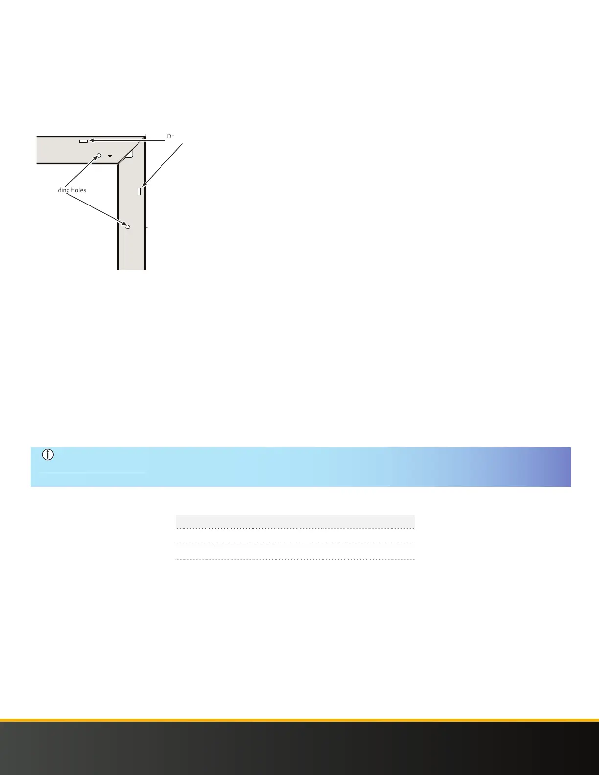
DRAINAGE HOLES
On the long and short sides of the REC frame small drainage holes can be found that allow humidity and water to exit the frame easily and
minimize the potential for damage (Fig. ). These are spaced . in from the corner of the panel. These holes must not be used for mounting
the panel, and they must not be covered by any part of the mounting structure. To enable effective drainage, the holes must remain fully
open and enable water egress during and after installation. The shape and dimensions of the drainage holes may vary depending on product
and/or frame design.
Fig. Drainage and Grounding Holes
25.6- 0 [650 - 0 mm]
GR
GR
GR
GR
0-25.6 in [0 - 650 mm]
9.8 - 4 in
[250 - 100 mm]
4 - 9.8 in
[100 - 250 mm]
9.8 - 4 in
[250 - 100 mm]
4 - 9.8 in
[100 - 250 mm]
25.6- 0 [650 - 0 mm]0-25.6 in [0 - 650 mm]
Grounding Holes
Drainage Holes
GROUNDING
A panel with exposed conductive parts is considered to be in compliance with IEC & UL only when it is electrically grounded in
accordance with the instructions presented below and the requirements of the National Electrical Code. When grounding a panel, it must be
done using an electrical connection from the panel frame. Local regulations may require grounding of the panels. Grounding must be done
using an electrical connection from the panel frame. REC solar panels have a clearly marked, small round Ø . in grounding hole positioned
near each corner of the panel on both the long side and the short side (Fig. ) and can be further identified by the grounding symbol stamped
in the frame next to it. Check all applicable requirements before beginning installation:
• Suitable grounding lugs must be used: Listed (KDER) ILSCO, GBL-DBT (tin plated) (E),
• Grounding cable size should be between - AWG (. mm - . mm),
• Attach grounds to the grounding holes in the panel frames,
• Fix lug to the frame using a star washer () and lock nut (), ensuring a conductive connection
• Follow the grounding device manufacturer’s installation instructions to ensure a safe and conductive connection, including
any supplementary hardware, e.g., star washer, and tighten according to recommended torque.
NOTE •
To avoid galvanic corrosion, galvanized or hot dipped zinc plated fasteners are preferred, however stainless steel
fastening materials are equally suitable.
• Negative grounding of the panels is not required by REC.
Stranded
Fig. Grounding lug dimensions and fastening torque
Stranded
Stranded/Solid
Type
Torque (in-lbs)
Cross section (AWG)
-
-
CONNECTIONS AND CONNECTORS
The connectors used on REC panels are indicated in the Panel Characteristics at the rear of this manual. The connector IP rating is only valid
when correctly connected. All connectors and cables must be secure and tight as well as electrically and mechanically sound. UV-resistant
cables and connectors approved for outdoor use must be used. Conductor gauge must be chosen to ensure DC power losses (voltage drop)
are kept to a minimum (<).
Observe all local regulations when selecting cables.
• For string connections, use minimum AWG ( mm) copper wires insulated for a maximum operating temperature of
°F (°C)
• Avoid exposing cables to direct sunlight and permanent tension.
 Loading...