-
REC Installation Manual - Module REC Alpha - IEC61215/IEC61730
Ref: PM-IM-23
REC Installation Manual - Module REC Alpha - IEC61215/IEC61730
Ref: PM-IM-23
Rev: . US
REC Installation Manual - Module REC Alpha - IEC/IEC
Ref: PM-IM-
Rev: . US
-
• In order to ensure a safe connection between panels and BOS equipment, the following instructions must be followed to
protect the connections from the elements.
WARNING • Safety is paramount when working with electrical connectors.
• Ensure that any installation work is not carried out on live or load-carrying parts.
•
Connections must not be disconnected under load and the system must be isolated from the grid before carrying
out any maintenance or repair work.
CONNECTORS
To ensure connector compatibility and reduce the potential for damage to the panels and the wider installation, REC only permits the mating
of connectors of the same manufacturer, type, and system rating (like-for-like).
NOTE
Some countries and/or regions have specific regulations regarding the mating of connectors. Installers are responsible
for ensuring the compliancy of the system with such local regulations.
CUTTING THE CABLES
The cutting of cables is only permitted in order to replace a factory-installed connector with another brand of connector to ensure ‘like-for-
like’ mating when connected to a non-REC external device. All other changes are prohibited and will invalidate the REC warranty.
• The connector replacement procedure must be carried out correctly and according to the replacement connector manufac-
turer’s instructions.
• The selected replacement connector must also fulfil all relevant technical specifications and be certified according to ap-
plicable standards (e.g., EN , IEC or UL ) to ensure they are fit for purpose and safety.
• Use of any chemicals or lubricants on the connectors or contacts may only be carried out in line with the connector manu-
facturer’s instructions.
The REC warranty does not extend to cover any fault traceable to the replaced connectors. Any other modification to the panel is prohibited,
including the opening of the junction box, unless explicitly authorized by REC. Doing so will invalidate the warranty.
CABLE MANAGEMENT
To ensure a long life span of the cables and reduce the potential for damage to the cables, follow the instructions below:
• To prevent stress on the junction box casing, ensure the cable exits the junction box in a
straight line before any bend in the cable and ensure cables are free from any external load,
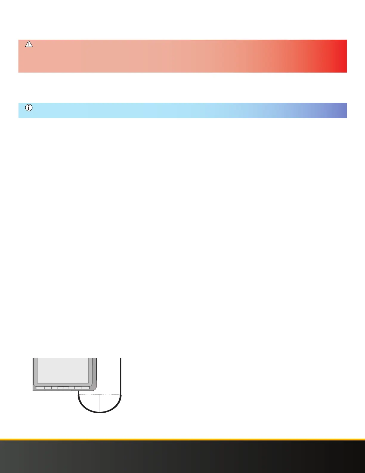
The cables must have a minimum bending radius of . in ( mm) to avoid damage to the insulation (Fig. ),
• Ensure cables do not hang loose where they may be damaged through friction or stress, e.g., caused by mechanical abrasion
or grazing animals,
• Protect connectors from falling or dropping water by locating them directly beneath a panel,
• Cables must be firmly secured to the structure, without over-tightening, as this can deform the cable insulation using
UV-resistant cables,
• When securing the connector, place it so that it has with sufficient air circulation all around. This allows the connector to dry
effectively and avoids the risk of damage or degradation of the connection,
• Secure the cable either side of the connectors to ensure no stress is exerted on the connector casing or cable entry,
• To enable correct cooling and drying of the connectors, do not add extra protection to the connector, e.g., heat shrink,
grease or tape.
More detailed information is given in the Guide to Best Practice - Connections and Connectors which can be found via the REC online Down-
load Center (www.recgroup.com/downloads)
< 60 mm >
< 30 mm >
< 2.4 in>
< 1.2 in >
Fig. Minimum Cable Distance
 Loading...