-
REC Installation Manual - Module REC Alpha - IEC61215/IEC61730
Ref: PM-IM-23
REC Installation Manual - Module REC Alpha - IEC61215/IEC61730
Ref: PM-IM-23
Rev: . US
REC Installation Manual - Module REC Alpha - IEC/IEC
Ref: PM-IM-
Rev: . US
-
Clearance Gap
. - . in
- mm
. - . in
- mm
>. in
> mm
Clamping Zone
Design Load
Test Load
Design Load
Test Load
Design Load
Test Load
Long Side
Mounting
- in
- mm
-
+ Pa / - Pa
+ Pa / - Pa
+ Pa / - Pa
+ Pa / - Pa
- . in
- mm
+ Pa / - Pa
+ Pa / - Pa
+ Pa / - Pa*
+ Pa / - Pa
+ Pa / - Pa
+ Pa / - Pa
. - . in
- mm
+ Pa / - Pa
+ Pa / - Pa
+ Pa / - Pa*
+ Pa / - Pa
+ Pa / - Pa*
+ Pa / - Pa
. - in
- mm
+ Pa / - Pa
+ Pa / - Pa
+ Pa / - Pa*
+ Pa / - Pa
+ Pa / - Pa*
+ Pa / - Pa
- . in
- mm
+ Pa / - Pa
+ Pa / - Pa
+ Pa / - Pa*
+ Pa / - Pa
+ Pa / - Pa*
+ Pa / - Pa
Short Side
Mounting
- . in
- mm
-
+ Pa / - Pa
+ Pa / - Pa
+ Pa / - Pa
+ Pa / - Pa
. - . in
- mm
-
+ Pa / - Pa
+ Pa / - Pa
+ Pa / - Pa*
+ Pa / - Pa
Long Side
Mounting
- in
- mm
-
+ Pa / - Pa
+ Pa / - Pa
+ Pa / - Pa*
+ Pa / - Pa
- . in
- mm
+ Pa / - Pa
+ Pa / - Pa
+ Pa / - Pa*
+ Pa / - Pa
+ Pa / - Pa*
+ Pa / - Pa
. - . in
- mm
+ Pa / - Pa
+ Pa / - Pa
+ Pa / - Pa*
+ Pa / - Pa
+ Pa / - Pa*
+ Pa / - Pa
. - in
- mm
+ Pa / - Pa
+ Pa / - Pa
+ Pa / - Pa*
+ Pa / - Pa
+ Pa / - Pa*
+ Pa / - Pa
- . in
- mm
+ Pa / - Pa
+ Pa / - Pa
+ Pa / - Pa*
+ Pa / - Pa
+ Pa / - Pa*
+ Pa / - Pa
Short Side
Mounting
- . in
- mm
-
+ Pa / - Pa
+ Pa / - Pa
+ Pa / - Pa
+ Pa / - Pa
. - . in
- mm
-
+ Pa / - Pa
+ Pa / - Pa
+ Pa / - Pa*
+ Pa / - Pa
Min.
2
5 m
m
Max
.
Min.
1
00
mm
Max
.
200 mm
Rail length under module - mm
Rail length under module - mm
MOUNTING REC ALPHA PURE PANELS WITH SHORT RAILS
A short rail (or other short support structure) has a minimum length of mm and does not span the complete underside of a panel.
Clamping of REC Alpha Pure Series panels using short rails
375 mm [14.8 in]
700 mm [27.5 in]
505 mm [19.9 in]
300 mm [11.8 in]
200 mm [7.9 in]
0
255 mm [10.0 in]
0
300 mm [11.8 in]
200 mm [7.9 in]
0
300 mm [11.8 in]
200 mm [7.9 in]
0
300 mm [11.8 in]
200 mm [7.9 in]
0
610 mm [24.0 in]
375 mm [14.8 in]
700 mm [27.5 in]
505 mm [19.9 in]
0
255 mm [10.0 in]
610 mm [24.0 in]
NOTE
Once a module is secured in each of the zones , additional clamps, i.e., ≥, may be freely located on panel frame without affecting the warran-
ty. Loads marked with a * were not certified as part of IEC / testing; these have been evaluated by REC’s internal testing process.
CAUTION
The center point of each clamp and the minimum grip length must be fully located in the same clamping zones to be rated to that load. If the
panel is secured in zones with diff erent load values, it is rated to the lowest load value only.
Fig. -
Clearance Gap
. - . in
- mm
. - . in
- mm
>. in
> mm
Clamping Zone
Design Load
Test Load
Design Load
Test Load
Design Load
Test Load
Long Side
Mounting
. - . in
- mm
+ Pa / - Pa
+ Pa / - Pa
+ Pa / - Pa
+ Pa / - Pa
+ Pa / - Pa
+ Pa / - Pa
Short Side
Mounting
. - . in
- mm
+ Pa / - Pa
+ Pa / - Pa
+ Pa / - Pa
+ Pa / - Pa
+ Pa / - Pa
+ Pa / - Pa
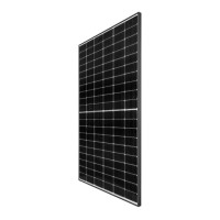
SIX POINT MOUNTING: REC ALPHA PURE
A six-point mounting configuration secures the panel on three continuous rails (or other support structures) with three clamps on each side of the
panel in the zones marked below:
Six-point mounting configuration clamping zones: REC Alpha Pure Series
NOTE
Once a module is secured in each of the zones , additional clamps, i.e., ≥, may be freely located on panel frame without affecting the warran-
ty. Loads marked with a * were not certified as part of IEC / testing; these have been evaluated by REC’s internal testing process.
CAUTION
The middle rail must not be installed on the side of the junction box where the cables exit.
A total of three continuous rails (or other support structures) must be used to secure the panel.
The center point of each clamp and the minimum grip length must be fully located within the marked zone to be rated to the given value.
GR
GR
GR
GR
760 mm [29.9 in] - 840 mm [33.1 in]
100 mm [3.9 in] - 430 mm [16.9 in] 430 mm [16.9 in] - 100 mm [3.9 in]
 Loading...