-
REC Installation Manual - Module REC Alpha - IEC61215/IEC61730
Ref: PM-IM-23
REC Installation Manual - Module REC Alpha - IEC61215/IEC61730
Ref: PM-IM-23
Rev: . US
REC Installation Manual - Module REC Alpha - IEC/IEC
Ref: PM-IM-
Rev: . US
-
Clearance Gap
. - . in
- mm
. - . in
- mm
>. in
> mm
Clamping Zone
Design Load
Test Load
Design Load
Test Load
Design Load
Test Load
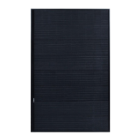
LongSide
Mounting
. - . in
- mm
+ Pa / - Pa
+ Pa / - Pa
+ Pa / - Pa*
+ Pa / - Pa
+ Pa / - Pa*
+ Pa / - Pa
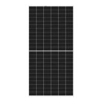
ShortSide
Mounting
. - . in
- mm
-
+ Pa / - Pa
+ Pa / - Pa
+ Pa / - Pa
+ Pa / - Pa
. - . in
- mm
-
+ Pa / - Pa
+ Pa / - Pa
+ Pa / - Pa*
+ Pa / - Pa
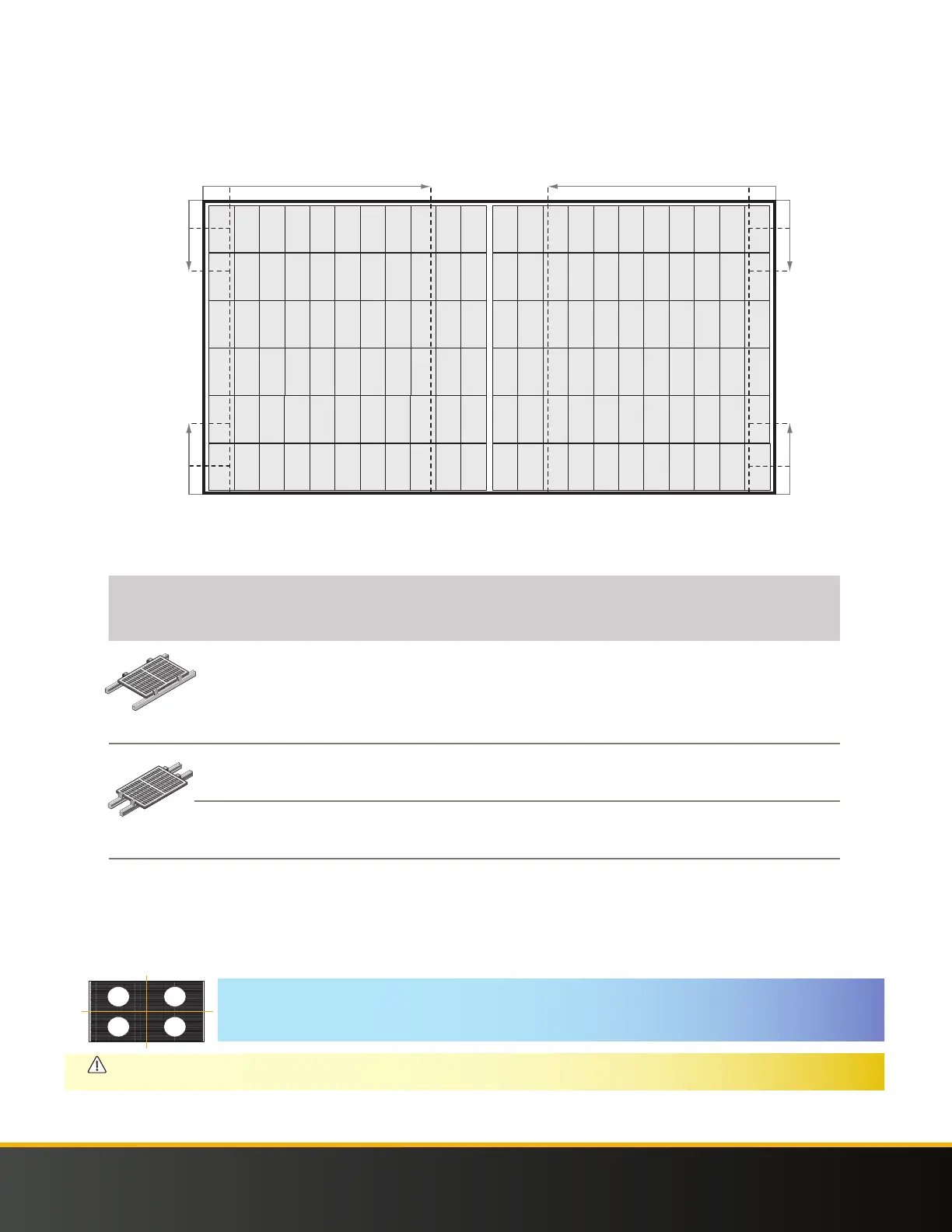
MOUNTING REC ALPHA PURE SERIES PANELS WITH CONTINUOUS RAILS PARALLEL TO LONG SIDE OF THE PANEL
A continuous rail (or other support structure) spans the complete underside of the panel
Clamping of REC Alpha Pure Series panels with Rails parallel to the Long Side of the Panel
4 in
0
0
0
0
4 in
9.85 in
9.85 in
4 in
9.85 in
9.85 in
4 in
0
0
750 mm
100 mm
0
0
0
0
100 mm
250 mm
250 mm
100 mm
250 mm
250 mm
100 mm
90 mm
0
750 mm
90 mm
0
29.5 in
0
3.5 in
0
29.5 in
3.5 in
NOTE
Once a module is secured in each of the zones , additional clamps, i.e., ≥, may be freely located on panel frame without affecting the warran-
ty. Loads marked with a * were not certified as part of IEC / testing; these have been evaluated by REC’s internal testing process.
CAUTION
The center point of each clamp and the minimum grip length must be fully located in the same clamping zones to be rated to that load. If the
panel is secured in zones with diff erent load values, it is rated to the lowest load value only.
Fig. -