-
REC Installation Manual - Module REC Alpha - IEC61215/IEC61730
Ref: PM-IM-23
REC Installation Manual - Module REC Alpha - IEC61215/IEC61730
Ref: PM-IM-23
Rev: . US
REC Installation Manual - Module REC Alpha - IEC/IEC
Ref: PM-IM-
Rev: . US
-
Clearance Gap
. - . in
- mm
. - . in
- mm
>. in
> mm
Clamping Zone
Design Load
Test Load
Design Load
Test Load
Design Load
Test Load
. - . in
- mm
+ Pa / - Pa
+ Pa / - Pa
+ Pa / - Pa
+ Pa / - Pa
+ Pa / - Pa
+ Pa / - Pa
. - . in
- mm
+ Pa / - Pa
+ Pa / - Pa
+ Pa / - Pa
+ Pa / - Pa
+ Pa / - Pa
+ Pa / - Pa
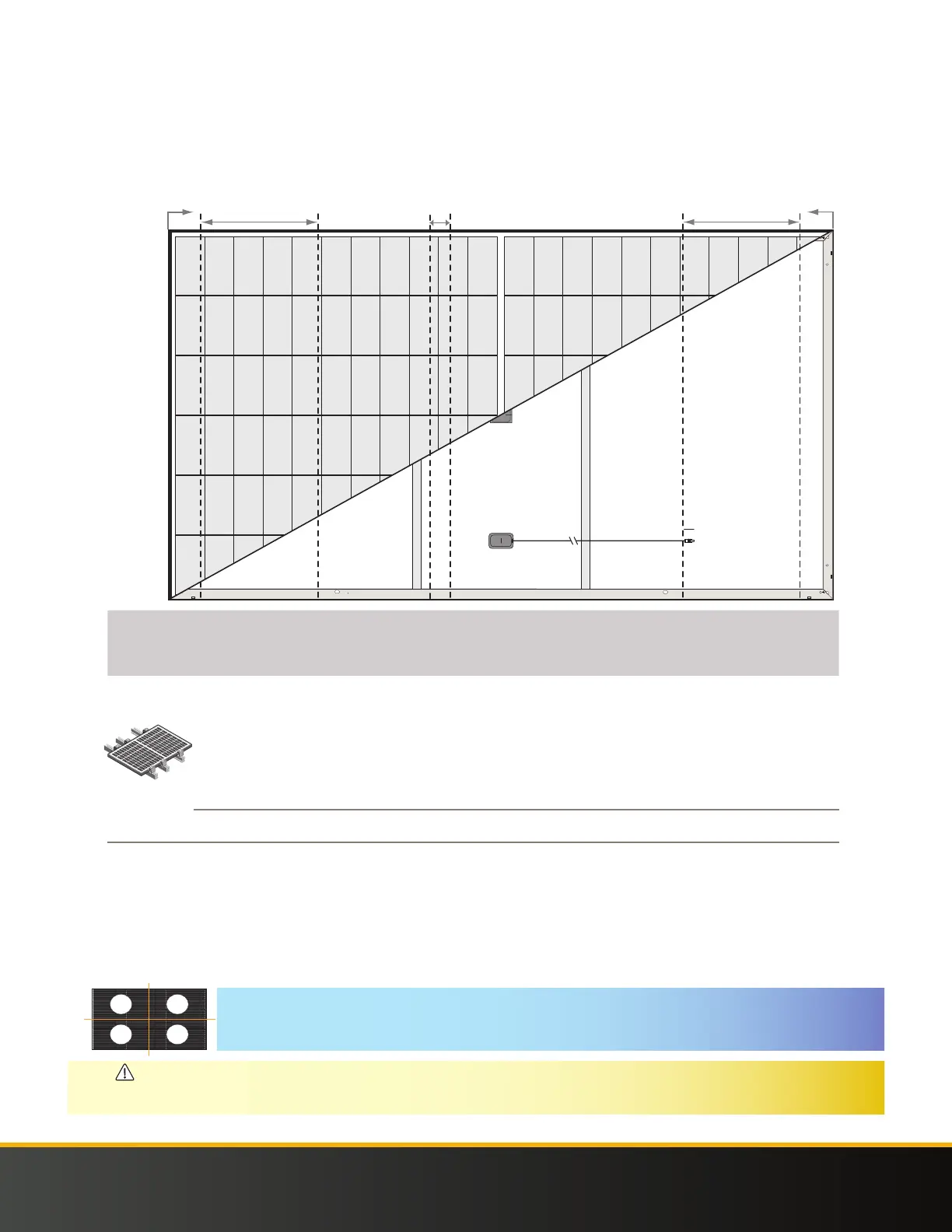
SIX POINT MOUNTING: REC ALPHA PURE
A six-point mounting configuration secures the panel on three continuous rails (or other support structures) with three clamps on each side of the
panel in the zones marked below:
Six-point mounting configuration clamping zones: REC Alpha Pure Series
0
430 mm
750 mm
100 mm
800 mm
0
430 mm
100 mm
0
16.9 in
29.5 in
3.9 in
31.5 in
0
16.9 in
3.9 in
NOTE
Once a module is secured in each of the zones , additional clamps, i.e., ≥, may be freely located on panel frame without affecting the war-
ranty. Loads marked with a * were not certified as part of IEC / testing; these have been evaluated by REC’s internal testing pro-
cess.
CAUTION
• The middle rail must not be installed on the side of the junction box where the cables exit.
• A total of three continuous rails (or other support structures) must be used to secure the panel.
• The center point of each clamp and the minimum grip length must be fully located within the marked zone to be rated to the given value.
Fig. -