6. Using the Router Table
WARNING:
Before attempting to make adjustments
to any settings make sure that the
power supply to the machine is
switched off and the supply cord is
removed from the outlet. Serious injury
may occur if the router is started while
making these adjustments.
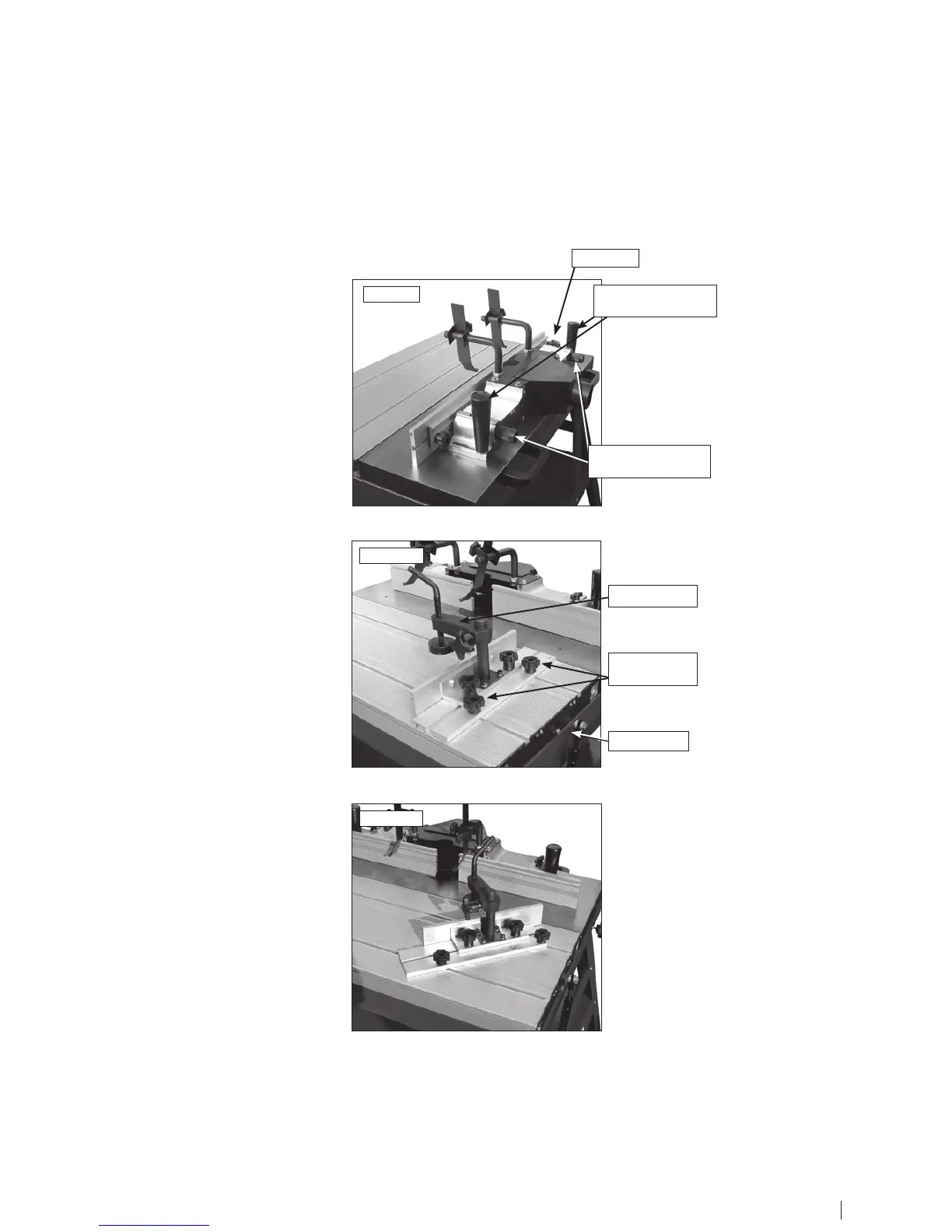
Fence Operation
1. The fence assembly is locked on the
table by the two lock handles.
2. To move the right hand fence half,
forward and backward to adjust the depth
of cut, turn the depth adjustment knob.
3. Loosen the wing nut before turning the
adjustment knob. Tighten it securely after
adustment.
4. To adjust the opening between the
right and left fence halves first release the
opening adjustment knob. Move the fence
halves to the correct position according to
the size of the router bit.
Sliding Table
1. Use the work clamp to fix the
workpiece to the sliding table.
2. The push plate position can be set
by loosening the push plate lock knobs,
adjusting the position, then retightening
the knobs.
3. The sliding table can be made immobile
by setting the lock tabs on the ends of the
sliding table.
Tilting the Push Plate to 45°
1. Loosen and take out the inside lock
knob on the push plate.
2. Tilt the push plate until the predrilled
hole on the push plate is aligned with the
middle T-slot on the sliding table.
3. Replace the inside lock knob to lock
the push plate at a 45° angle. The push
plate is now angled for bevelled routing.
Fig.4.1
Fig.4.2
Fig.4.3
12 13
depth adjustment
knobs
depth adjustment
knobs
work clamp
push plate
lock knobs
lock tabs
wing nut
 Loading...