NOTICE: Failure to read and comply with all warnings, cautions and instructions prior to starting installation
may cause personal injury and/or property damage and void the warranty. All wiring must follow
NEC guidelines and local codes.
WARNING: Shut off power to unit prior to performing electrical work.
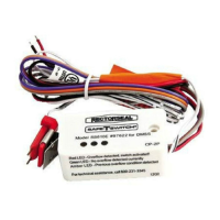
1. (Internal Installation) Place CPU inside evaporator enclosure or line set cover.
(External Installation) Mount CPU to a surface using double-sided tape or fasten using a screw.
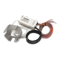
2. Route lead wire into wiring space. Route Sensor into evaporator space. Do not cut Sensor wire.
If necessary, remove bracket from Sensor before routing.
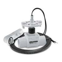
3. Sensor Mounting to Pan (Figure 1a):
a. Attach Sensor to Pan Bracket.
b. Clip the Pan Bracket to where water level will be the highest in the evaporator condensate pan, press
firmly in place
c. Position the Wires up and Probe Pins down.
d. Adjust Sensor height by pushing the Sensor into the Pan Bracket. The Pan Bracket has a one-way
ratchet mechanism. If the Sensor is set too low in the pan, push the Sensor from the lead side until
it disengages from the Pan Bracket, then reset. Adjust the sensor so that the Probe Pins are below
the rim of the condensate pan. The switch will trip when water level reaches Probe Pins.
4. Sensor Mounting to Coil (Figure 1b):
a. Attach Sensor to Coil Bracket. The Coil Bracket has 2 optional clips, one for regular 7mm coil and the
other for 5mm coil. Choose clip size according to the actual coil tube diameter.
b. Clip the Coil Bracket onto evaporator coil. Insert the Bracket Clip between the fins or at the coil U-bend.
c. Position the Wires up and Probe Pins down.
d. Adjust Sensor height by moving Sensor to where water level will be the highest in the evaporator
condensate pan. Adjust the Sensor so that the Probe Pins are below the rim of the condensate pan.
The switch will trip when water level reaches Probe Pins.
5. Wiring Option 1*: Interfering Communication Line (Figure 2)
a. CONFIRM MAIN POWER SUPPLY IS SHUT OFF. Read air conditioner installation manual for the wiring
terminal layout. Connect “Power Input” wires to indoor unit power supply terminal.
b. Cut the communication wire of the indoor unit. Connect “COM-NC” and “NC” wires as shown in
Figure 2. Insulate the exposed “COM-NO” and “NO” wire using insulating tape.
(WARNING: Electric shock hazard. Failure to insulate unused switch wires may cause personal injury and/or property damage.
c. Use a wire nut when connecting wire to wire.
INSTALLATION INSTRUCTIONS:
6. Wiring Option 2*: Interfering Power Line (Figure 3)
a. CONFIRM MAIN POWER SUPPLY IS SHUT OFF. Read air conditioner installation manual for the wiring
terminal layout. Connect “Power Input” wires to indoor unit power supply terminal.
b. Cut power wire of the indoor unit. Wire “COM-NC” and “NC” wires as shown in Figure 3. Insulate the
“COM-NO” and “NO” wire using insulating tape.
(WARNING: Electric shock hazard. Failure to insulate unused switch wires may cause personal injury and/or property damage.
c. Use a wire nut when connecting wire to wire.
Figure 2: Wiring Option 1*:
Interfering Communication Line
Figure 3: Wiring Option 2*:
Interfering Power Line
WARNING: This device must be installed strictly in accordance with manufacturer’s instructions (to ensure proper
operation)and in accordance with all applicable local plumbing, drainage and electrical codes.
WARNING: Electric shock hazard. Disconnect power supply before installing this product to avoid electrical shock
and/or equipment damage.
CAUTION: This device will not detect clogs occurring upstream from the installation point.
CAUTION: Branch circuit protection shall be provided using a UL listed branch circuit protection device rated minimum
250V AC/100V DC, maximum 1A as appropriate for the supply source.
CAUTION: This product is intended for use in water only. Not for use in the presence of flammable liquids or vapors.
CAUTION: Refer to the appropriate HVAC equipment operation manual prior to installing this product.
CAUTION: Do not use on dual compressor systems.
SPECIFICATIONS: Power/Switch Wire Length: 2'. Sensor Wire Length: 4'. Power Input: 110-230VAC. AC Switching
Capacity: 0-250VAC, 5A, 1250VA Max. DC Switching Capacity: 0-30VDC, 5A, 150W Max. Switch
Method: Normally Open (NO) and Normally Closed (NC).
7. Wiring Option 3: Interfering Built-in Shut-off Terminal
a. CONFIRM MAIN POWER SUPPLY IS SHUT OFF.
b. Read air conditioner installation manual for the location and wiring of external shut-off terminal (or
overflow switch terminal). Wiring harness may be required to connect our switch to these terminals.
If the wiring harness doesn’t come with the air conditioner unit, please contact air conditioner
manufacturer for assistance.
c. Read air conditioner installation manual to find out the shut-off signal type. It is either Normally Closed
or Normally Open. For Normally Closed, wire “COM-NC” and “NC” wires to the shut-off terminal. For
Normally Opened, wire “COM-NO” and “NO” wires to the shut-off terminal.
d. Use a wire nut when connecting wire to wire
1. Turn on main power supply to air conditioner.
2. The CPU will display a Green Light. If the Green LED does not come on, turn off power and check switch wiring.
3. Start air conditioner indoor unit. If the indoor unit does not come on, turn off power and check switch wiring.
4. Test the switch by shorting across the Probes Pins with water or a metallic conductor. If wired correctly,
the indoor unit will stop and the Red LED will come on after 5-10 seconds. When released, after 5-10
seconds the Red LED will go off, the Green and Amber LEDs will come on and the indoor unit will restart.
If the switch does not cycle, turn off power and check switch wiring. To turn off Amber light, see manual
history reset tag on CPU wire.
5. Test the Sensor position by turning on the air conditioner to produce a normal condensate flow. If the
Sensor is in water, the switch will activate and shut down the unit. Next, block the drain to allow the pan
to fill with water. The switch should activate before the pan overflows. If necessary, adjust Sensor height
as described in Installationsection above.
TESTING
*WIRING OPTION 1 AND 2 ILLUSTRATE WIRING TERMINAL OF A TYPICAL DUCTLESS MINI-SPLIT SYSTEM. SYSTEMS FROM DIFFERENT MANUFACTURERS MAY BE
WIRED DIFFERENTLY. PLEASE REFER TO AIR CONDITIONER’S MANUALS FOR CORRECT WIRING TERMINAL LAYOUT AND WIRING INSTRUCTIONS OR USING THE
QR CODE ON BACK OF PACKAGE, CONNECT TO RECTORSEAL‘S WEBSITE FOR MORE WIRING OPTIONS.
6. Cableado Opción 2*: Línea de Interferencia de alimentación (Figura 3)
a. ASEGURESE DE QUE LA FUENTE DE ALIMENTACIÓN ESTE APAGADA. Lea el manual de instalación de aire
acondicionado para el diseño de terminales de cableado. Conecte los cables “Power Input” a la terminal
de fuente de alimentación de la unidad interior.
b. Corte el cable de comunicación de la unidad interior. Conecte los cables “COM-NC” y “NC”, como
se muestra en la Figura 3. Insular los cables “COM-NO” y “NO” con cinta aislante.
(ADVERTENCIAPeligro de electrocución El incumplimiento de aislar los cables no utilizados del interruptor puede
causar lesiones personales y / o daños a la propiedad.
c. Use una tuerca de cable para conectar cable a cable.
1. (Instalación Interna) Coloque el CPU adentro del compartimiento del evaporador o en la cubierta de los conductos.
(Instalación Externa) Montar la CPU a una superficie con cinta de doble cara o sujetar con un tornillo.
2. Conduzca el juego de cables dentro del espacio del cableado. Conduzca el sensor dentro del spacio del
evaporador. No corte el cable del sensor. Si es necesario, remueva el soporte del sensor antes del enrutamiento.
3. Montaje del Sensor de Pan (Figura 1a):
a. Conecte el Sensor a Pan Soporte.
b. Sujete el Soporte de la Bandeja donde el nivel del agua será el más alto en la bandeja de condensación
del evaporador, presione firmemente en su lugar.
c. Coloque los Cables arriba y los Pines de Sonda abajo.
d. Ajuste la altura del Sensor pulsando el Sensor en el Soporte de la Bandeja. El Soporte de la Bandeja tiene
un mecanismo de trinquete unidireccional. Si el Sensor está demasiado bajo en el sartén, empuje el sensor
del lado del conductor hasta que se desenganche del Soporte de la Bandeja, luego se borra. Ajuste el sensor
para que las Agujas del Detector estén debajo del borde de la bandeja de condensado. El interruptor se
disparará cuando el nivel del agua alcance las Agujas del Detector.
4. Montaje del Sensor de la Bobina (Figura 1b):
a. Conecte el Sensor al Soporte de la Bobina. El Soporte de la Bobina tiene 2 pinzas opcionales, uno para
la bobina regular de 7 mm y el otro para la bobina de 5 mm. Seleccione el tamaño clip de acuerdo con el
diámetro del tubo bobina real.
b. Sujete el Soporte de la Bobina a el evaporador. Inserte el Clip de Soporte entre las aletas para fijar en la
bobina o en el returno en “U” del evaporador.
c. Coloque los Cables arriba y los Pines de Sonda abajo.
d. Ajuste la altura del sensor moviendo el sensor a donde el nivel de agua será el más alto en la bandeja de
condensado del evaporador. Ajuste el sensor de modo que las Agujas del Detector estén debajo del borde de
la bandeja de condensado. El interruptor se disparará cuando el nivel del agua alcance las Agujas del Detector.
5. Cableado Opción 1*: Línea Interferir Comunicación (Figura 2)
a. ASEGURESE DE QUE LA FUENTE DE ALIMENTACIÓN ESTE APAGADA. Lea el manual de instalación de aire
acondicionado para el diseño de terminales de cableado. Conecte los cables “Power Input” a la terminal
de fuente de alimentación de la unidad interior.
b. Corte el cable de comunicación de la unidad interior. Conecte los cables “COM-NC” y “NC”, como
se muestra en la Figura 2. Insular los cables “COM-NO” y “NO” con cinta aislante.
(ADVERTENCI Peligro de electrocución El incumplimiento de aislar los cables no utilizados del interruptor puede
causar lesiones personales y / o daños a la propiedad.
c. Use una tuerca de cable para conectar cable a cable.
INSTRUCCIONES DE INSTALACIÓN:
AVISO: La falta de una lectura de todas las advertencias, precauciones e instrucciones antes de empezar la
instalación, y el incumplimiento de las mismas, podría causar lesiones en su persona y/o daños en
propiedad y anular la garantía. Todo el cableado debe seguir las pautas NEC y los códigos locales.
ADVERTENCIA: Desconecte la corriente a la unidad antes de realizar trabajos de electricidad.
Figure 1a: Installation on Drain Pan
Figura 1a: Instalacin en Pan de drenaje Figura 1b: Instalacin de aletas de la batera
Figure 1b: Installation on Coil Fins
Power Source
L2L1
Switch
Power
Input
Probe
Gray
(Com-NC)
Purple (NC)
1 2 3 4
RedBlack
CPU
1 2 3 4
Switched
Signal
Power Source
Switch
Gray
(Com-NC)
Purple
(NC)
Power
Input
Red Black
CPU
Probe
L1 L2
Power Source
L2L1
Switch
Power
Input
Probe
Gray
(Com-NC)
Purple (NC)
1 2 3 4
RedBlack
CPU
1 2 3 4
Switched
Signal
Power Source
Switch
Gray
(Com-NC)
Purple
(NC)
Power
Input
Red Black
CPU
Probe
L1 L2