Do you have a question about the RectorSeal SS1 and is the answer not in the manual?
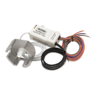
Step-by-step guide for mounting the Safe-T-Switch horizontally.
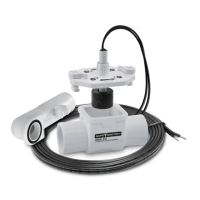
Step-by-step guide for mounting the Safe-T-Switch vertically.
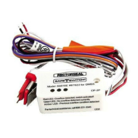
Instructions for connecting the Safe-T-Switch to the HVAC unit's wiring.
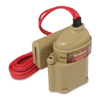
Procedure for using the cleanout tool to clear drain line blockages.
The RectorSeal Safe-T-Switch Model SS1 (Product Code 97632) is a low-voltage condensate overflow shut-off switch designed to prevent property damage from overflowing condensate pans in HVAC systems. It functions by detecting rising water levels in the condensate pan and interrupting the 24-volt control circuit of the HVAC unit, thereby shutting it down before an overflow occurs.
The Safe-T-Switch SS1 is an electromechanical device that utilizes a float mechanism to detect the presence of water. When the condensate pan fills to an unsafe level, the float rises, activating a switch that breaks the 24-volt circuit to the HVAC unit. This interruption can be wired to either the red (cooling/heating) or yellow (cooling only) circuit of the thermostat cable. Wiring it to the red circuit will shut down the entire unit, while wiring to the yellow circuit will allow the fan to continue running (which can help inhibit mold during long absences). The switch is designed for both horizontal and vertical installations, offering flexibility in placement depending on the specific HVAC system configuration and available space.
The SS1 can be installed in two primary orientations:
The sensitivity of the switch can be adjusted to ensure it triggers before the pan overflows. This can be achieved by:
The switch can be wired into either the red or yellow thermostat circuit:
The Safe-T-Switch SS1 is designed for easy maintenance and clog removal using the optional Safe-T-Switch SS1 Directional Cleanout Tool (not included with the switch itself but referenced in the manual).
| Brand | RectorSeal |
|---|---|
| Model | SS1 |
| Category | Switch |
| Language | English |