4
Drawing No. LP1159 Effective 06 2020
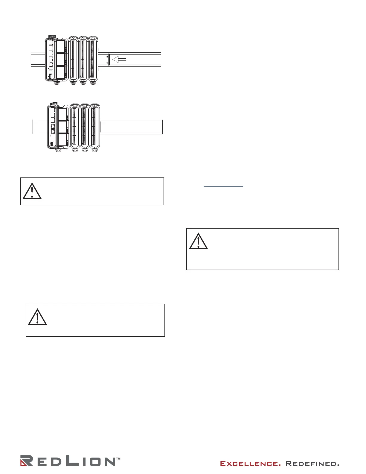
Figure 2 - Attach dust cap to last module
Figure 3 - Module Installation is complete.
SLED INSTALLATION
1. Prior to installing the Sled(s) for your DA70A Gateway
application, ensure that the Gateway is not receiving power.
2. Remove the carriage from the Gateway case by releasing the
two retaining latches and pulling straight out from Gateway.
3. Remove blank panel from the carriage slot of the target sled
installation location.
4. Install sled by aligning the two sled mounting hole fasteners,
with the Gateway mounting posts. Be sure locating holes on
bottom side of sled align with the locating pins on the
carriage, and the sled sits flush against the carriage.
5. Hand tighten the sled captive fasteners, or use a screwdriver
if necessary.
6. Repeat the above steps for any additional sleds.
7. Carefully align the carriage with Gateway base and press
carriage into the Gateway.
8. Close the retaining latches to ensure the carriage is fully
seated into the Gateway case.
POWER SUPPLY REQUIREMENTS
The DA70A Gateway requires a 12-24 VDC power supply. Your
unit may draw considerably less than the maximum rated power
depending upon the configuration and features being used. As
additional sleds and/or modules are used, your unit will draw
increasing amounts of power. Items that could cause increases in
current are modules, microSD card, communications sleds, and
other features programmed through software.
To ensure you do not exceed the capacity of your DA70A
Gateway host power supply, calculate the total power consumption
required for all planned accessories. Each module’s maximum
power consumption is listed in the Specifications of their Product
Bulletin. The total power available for modules is listed in the
specifications of the DA70A Gateway host.
It is very important that the power supply meets the following
requirements and is mounted correctly if the unit is to operate
reliably. Please take care to observe the following points:
– The power supply must be mounted close to the unit, with
usually not more than 6 feet (1.8 m) of cable between the
supply and the Gateway. Ideally, the shortest length possible
should be used.
– The wire used to connect the Gateway power supply should
be at least 22-gauge wire. If a longer cable run is used, a
heavier gauge wire should be used. The routing of the cable
should be kept away from large capacitors, inverters, and
other devices which may generate significant electrical noise.
– Use a power supply with an NEC Class 2 or Limited Power
Source (LPS) and SELV (safety extra-low voltage) rating. This
type of power supply provides isolation to accessible circuits
from hazardous voltage levels generated by a mains power
supply due to single faults. Safety extra-low voltage circuits
shall exhibit voltages safe to touch both under normal
operating conditions and after a single fault, such as a
breakdown of a layer of basic insulation or after the failure of
a single component has occurred.
– Peak efficiency (DA70A) occurs at the low side of the voltage
range (approx. 12 V), recommended for high temperature
applications.
Visit www.redlion.net for a complete list of our NEC Class 2
power supplies.
WIRING
All power, input and output (I/O) wiring must be in accordance
with Class I, Division 2 wiring methods and in accordance with
the authority having jurisdiction.
CONNECTING TO EARTH GROUND
Each DA70A has a chassis ground terminal on the top of the
unit. Your unit should be connected to earth ground. Steps should
be taken beyond connecting to earth ground to eliminate the
buildup of electrostatic charges.
The chassis ground is not connected to signal common of the
unit. Maintaining isolation between earth ground and signal
common is not required to operate your unit. But, other equipment
connected to this unit may require isolation between signal
common and earth ground. To maintain isolation between signal
common and earth ground care must be taken when connections
are made to the unit. For example, a power supply with isolation
between its signal common and earth ground must be used. Also,
plugging in a USB cable may connect signal common and earth
ground.
1
1
USB’s shield may be connected to earth ground at the host.
USB’s shield in turn may also be connected to signal common.
FACTORY RESET BUTTON
The factory reset button located in the lower left area of the
front of the unit can be used to clear the configuration. Hold in
the reset button at power up until the status ring LED turns bright
white. Click the button to cycle through colors on the status ring
LED. If left at white, the unit will boot its existing configuration,
and if left at red it will clear the units memory. Once the memory
is cleared, the user will need to use the default password printed
on the unit to access the configuration.
DIN RAIL
DIN RAIL
CAUTION: Follow standard ESD precautionary
procedures.
ATTENTION: Suivez les procédures de précaution
standard de décharge électrostatique.
CAUTION: Failure to properly align the carriage
can result in damage to the Sled connector pins.
ATTENTION: Si le chariot n’est pas correctement
aligné, les broches du connecteur du chariot
risquent d’être endommagées.
CAUTION: Only UL listed wiring with temperature
ratings greater than 90 °C permitted for Class I, Division
2, Zone 2 and ATEX/IECex installations.
ATTENTION: Seul le câblage homologué UL avec des
températures nominales supérieures à 90°C est autorisé
pour les installations de classe I, Division 2 , zone 2 et
ATEX/IECex.
 Loading...