EasyManua.ls Logo

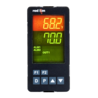
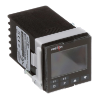
red lion PXU20020 User Manual

red lion PXU20020
47 pages
To Next Page IconTo Next Page
Page #1 background imageLoading...
Page #1 background image
PXU Series
Temperature/Process Controllers
For Firmware Version 1.5 or Above
Hardware Guide | Jan 2018
LP0932 | Revision E

Questions and Answers:

red lion PXU20020 Specifications

General IconGeneral
ModelPXU20020
Communication PortsRS-485
PowerAC Power
CertificationsCE, UL, cUL
TypeController
Input Voltage100 to 240 VAC
Input TypeThermocouple, RTD, Analog Voltage, Analog Current
Output TypeAnalog
DisplayDual LED
Dimensions48 x 48 mm
Power Consumption5 VA max
Humidity20% to 85% RH (non-condensing)

Summary

Safety Summary

General Description

Main Control

Describes PID, On/Off, Manual control modes and output capabilities.

Alarms

Details alarm configuration for high/low acting, deviation, and band alarms.

General Specifications

Sensor Input

Covers sample period, A/D converter, fail response, and rejection ratios.

Input Capabilities

Details accuracy, thermocouple types, impedance, and cold junction compensation.

Output Capabilities

Control Relay Outputs (OUT1/OUT2)

Control SSR Drive Output (OUT1)

Control Analog Output (OUT1)

EMC Installation Guidelines

Setting the Jumpers

Explains how to access and set jumpers for current and remote input types.

Installing the Controller

Wiring the Controller

Wiring Connections

Details rear terminal connections, conductor standards, and grounding.

Controller Power Connections

Guidance on clean power supply and protection for the controller.

Input Connections

Explains wiring for RTD, Thermocouple, CT, and Remote Input types.

Programming Loops

Display/Parameter/Hidden Loop Reference Table

Table listing parameters, descriptions, ranges, and factory settings across loops.

Display Loop

Display/Parameter/Hidden Loop Parameter Descriptions

PID Group

Allows selection of different PID parameter sets for various applications.

Active Setpoint Value

Displays and allows changing the active setpoint value or profile segment number.

Profile Time

Starting Profile

Starting Profile Segment

Output Power Offset

Proportional Band

Integral Time

Derivative Time

Integration Default

Alarm Value

Alarm Reset

Setpoint Select

Auto-Tune Start

Auto Control Mode

Programming: Configuration Loop

Module 1 - Input Parameters (1-17)

Covers configuration of input signal type, scaling, and filtering.

Input Signal Configuration

Setpoint Limits

Setpoint Low Limit

Defines the minimum programmable low setpoint value to restrict the range.

Setpoint High Limit

Defines the maximum programmable high setpoint value to restrict the range.

Remote Input Configuration

Module 2 - Output Parameters (2-DP)

Output 1 Configuration

Configures cycle time, power limits, fail level, and analog scaling for Output 1.

Output 2 Configuration

Configures cycle time, power limits, and fail level for Output 2.

Analog Low Scaling

Analog High Scaling

Module 3 - Lockout Parameters (3-LE)

Access Code

Manages access levels to Display, Parameter, Hidden, and Configuration Loops.

Module 4 - Alarm Parameters (4-AL) (Optional)

Available Alarm Actions

Alarm 1 Configuration

Alarm 1 Action

Selects the action for Alarm 1 (e.g., High, Low, Deviation).

Alarm 1 Annunciator

Sets the alarm annunciator to Normal or Reverse indication.

Alarm 1 Reset Mode

Defines alarm reset behavior as Automatic or Latched.

Alarm 1 Standby

Enables or disables standby mode to prevent nuisance alarms after power-up.

Alarm 1 Value

Sets the alarm threshold value based on process units or degrees.

Alarm 2 Configuration

Alarm 3 Configuration

Module 5 - Control Parameters (5-CP)

PID Group Management

Selects which PID parameter group (1-6) to edit or use for auto-selection.

PID Tuning Parameters

Includes Integral Time, Derivative Time, Integration Default, and Proportional Band.

Module 6 - Profile Module Parameters (6-Pr)

Module 7 - Serial Communications Parameters (7-5C)

Communication Protocol Settings

Configures communication type, baud rate, data bits, parity, and unit address.

Serial Communications

Modbus Registers

Lists common Modbus registers for reading and writing PXU parameters.

Troubleshooting

Control Mode Explanations

On/Off Control

Describes how the process oscillates around the setpoint with hysteresis for stability.

PID Control

Explains PID control using Proportional, Integral, and Derivative algorithms for precise control.

PID Tuning Explanations

Auto-Tune

Details how Auto-Tune automatically determines PID parameters for optimal control.

Auto-Tune Progress

Auto-Tune Operation (Reverse Acting)

To Quicken Response

PID Adjustments

Process Response Extremes

Manual Tuning

Digital Potentiometer

Setpoint Profile Operation

Controlling a Profile

PXU Modbus Register Table

Frequently Used Registers

Lists common Modbus registers for reading and writing PXU parameters.

Related product manuals