EasyManua.ls Logo

red lion DLC00001 - User Manual

red lion DLC00001
28 pages
Print Icon
To Next Page IconTo Next Page
Loading...
1
MODULAR BUILDING BLOCK FOR MULTI-ZONE PROCESS CONTROL
TWO INDEPENDENT PID CONTROL LOOPS
PID CONTROL WITH REDUCED OVERSHOOT
UNIVERSAL INPUTS ACCEPT TC, RTD, 0-10 V AND 0/4-20 mA SIGNALS
TWO DC ANALOG OUTPUTS (OPTIONAL)
WINDOWS
®
CONFIGURATION SOFTWARE
RS485 MODBUS™ PROTOCOL
CHANNEL B CAN BE ASSIGNED AS A SECOND ANALOG INPUT TO
CHANNEL A FOR REMOTE SETPOINT OPERATION
SETPOINT CONTROLLER OPTION FOR TIME VS. TEMP./PROCESS
(RAMP/SOAK) AND SPECIAL BATCH/RECIPE APPLICATIONS
SQUARE ROOT EXTRACTION FOR FLOW SENSOR APPLICATIONS
GENERAL DESCRIPTION
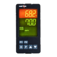
The Model DLC, Dual Loop Controller, is a full featured, DIN rail mounted,
dual input PID controller. The DLC is designed as a modular building block for
multi-zone process control applications. The controller has two independent
“A” & “B” input channels. Each channel’s input can be configured to accept a
wide range of thermocouple, RTD, 0-10 V, 0/4-20 mA, or resistive signals. Each
channel can also be configured to extract the square root of the input in both
process voltage or process current modes for applications such as flow
measurement using a differential flow sensor.
Channel B can be assigned as a Remote Setpoint for Channel A. The two
time-proportioning or DC Analog outputs can be programmed to control two
independent processes. The two alarms per channel can be configured for
various alarm modes, or provide a secondary control output for heat/cool
applications.
The control and alarm outputs are N channel open drain MOSFETs capable
of switching up to 1 Amp DC. For applications requiring larger loads or A/C
loads, several DIN rail mount relays are available.
The controller operates in the PID Control Mode for both heating and
cooling, with on-demand auto-tune, that establishes the tuning constants. The
PID tuning constants may be fine-tuned through the serial interface. The
controller employs a unique overshoot suppression feature, which allows the
quickest response without excessive overshoot. The controller can be transferred
to operate in the Manual Mode, providing the operator with direct control of the
output, or the On/Off Control Mode with adjustable hysteresis.
The controllers high density packaging and DIN rail mounting saves time
and panel space. The controller snaps easily onto standard top hat (T) profile
DIN rails.
SAFETY SUMMARY
All safety related regulations, local codes and instructions that appear in the
manual or on equipment must be observed to ensure personal safety and to
prevent damage to either the instrument or equipment connected to it. If
equipment is used in a manner not specified by the manufacturer, the protection
provided by the equipment may be impaired.
Do not use the controller to directly command motors, valves, or other
actuators not equipped with safeguards. To do so can be potentially harmful to
persons or equipment in the event of a fault to the controller. An independent
and redundant temperature limit indicator with alarm outputs is strongly
recommended.
ALARMS
The DLC’s two solid-state alarms can be configured independently for
absolute high or low acting with balanced or unbalanced hysteresis. They can
also be configured for deviation and band alarm. In these modes, the alarm
trigger values track the setpoint value. Adjustable alarm trip delays can be used
for delaying output response. The alarms can be programmed for Automatic or
Latching operation. Latched alarms must be reset with a serial command. A
standby feature suppresses the alarm during power-up until the temperature
stabilizes outside the alarm region. The outputs can also be manually controlled
with Modbus register or coil commands.
SETPOINT CONTROLLER OPTION
The Setpoint Controller option is suitable for time vs. temperature/process
control applications. The controller allows a profile of up to 20 ramp/soak
segments. Profile conformity is assured by using the Error Band Mode and
Error Band parameter. The Profile Cycle Count allows the profile to run
continuously or a fixed number of cycles. Power-on options automatically stop,
abort, start, resume, or pause a running profile.
ORDERING INFORMATION
MODEL NO. DESCRIPTION PART NUMBERS
DLC
Dual Loop Controller DLC00001
Dual Loop Controller w/ 2 Analog Outputs DLC01001
Dual Setpoint Controller w/ 2 Analog Outputs DLC11001
SF PC Configuration Software for Windows SFDLC
CBPRO Programming Interface Cable CBPRO007
CBJ Cable RJ11 to RJ11 (6 inch jumper) CBJ11BD5
DRR RJ11 to Terminal Adapter DRRJ11T6
RS485 to RJ11 Cable CBLRLC00
See our RSRLYB, RLY6, and RLY7 literature for details on DIN rail
mountable relays.
CAUTION: Risk of Danger.
Read complete instructions prior to
installation and operation of the unit.
DUAL LOOP CONTROLLER
Bulletin No. DLC-J
Drawing No. LP0495
Released 09/16
Tel +1 (717) 767-6511
Fax +1 (717) 764-0839
www.redlion.net
OPTIONAL
BOTH FLASHING
ALL FLASHING = CHECKSUM ERROR
0-10V, 0-20mA
ANALOG OUTPUT 1
0-10V, 0-20mA
ANALOG OUTPUT 2
JUMPERS
INPUT ERROR
RS485
MODBUS
PROTOCOL
CH B ALM
=
6
0-10V, 0-20mA
0-10V, 0-20mA
TC+ OR RTD
INPUT COMMON
TC+ OR RTD
INPUT COMMON
RTD EXC.
TBB
12
RTD EXC.
435
INPUTS
CH B CH A
INPUTS
DEFAULT SERIAL SETTING
OUT +
OUT -
789
OUT +
OUT -
1110
PWR/COMM.
INPUT ERROR
BOTH FLASHING
CH A ALM
AUTOTUNE
CH B OP
CH A OP
=
SETTINGS
FACTORY
JUMPER
MODEL DLC
AL2/OP2
AL2/OP2
OUTPUT COMMON
OUTPUTS
10V
20mA
RTD
10V
RTD
20mA
DC- / (AC)
DC+ / (AC)
+24VDC OUT
I1-
I1+
V1+
V1-
V2-
V2+
I2+
I2-
OUTPUTS
CH A CH B
5
OP1
TBA
1
32
4 6
AL1
78
OP1
109
AL1
YORK, PA. MADE IN U.S.A.
4.47 (114)
(102)
1.97
4.02
(50)
RED LION CONTROLS
AC 24V ±10%, 50/60 Hz, 15VA
DC 18-36V, 13W
POWER: (FULL LOAD)
MODEL DLC
RED LION CONTROLS
!
EQUIPMENT
CONTROL
PROCESS
3RSD
DIMENSIONS In inches (mm)
C
US LISTED
U
L
R
3RSD
PROCESS CONTROL EQUIPMENT

Questions and Answers

  • C
    Chad HicksAug 14, 2025
    Why is the process value not changing or incorrect on my red lion DLC00001?
    • J
      Joseph CampbellAug 14, 2025
      The process value might not be changing or could be incorrect on your Red Lion Controller due to several reasons. It could be due to an incorrect input signal channel, incorrect programming, or faulty connections. You should check the input signal connections and signal level. Also, verify the proper channel setup, readings, and connections. Finally, review the input setup, scaling values, and re-download the configuration.
  • C
    Charles AllenAug 18, 2025
    How to fix a red lion DLC00001 when the power LED will not light?
    • J
      Jon BrownAug 18, 2025
      If the power LED on your Red Lion Controller doesn't light up, the issue probably lies with the controller's power supply. Check the controller's power connections and voltage level to ensure they are correct.
  • M
    Morgan PerryAug 20, 2025
    What to do if alarms are not functioning properly on red lion DLC00001?
    • J
      josephtuckerAug 21, 2025
      If the alarms on your Red Lion Controller are not working correctly, this could be due to calculated trigger points exceeding +32000 or falling below -32000. To resolve this, adjust the alarm value, alarm hysteresis, and setpoint value to ensure valid trigger points are used.
  • A
    austin64Aug 25, 2025
    Why will my red lion DLC00001 not communicate (Comm. LED not flashing)?
    • J
      Jessica MillerAug 25, 2025
      If your Red Lion Controller is not communicating and the Comm. LED is not flashing, the problem could stem from: * Incorrect serial settings on either the DLC or computer port. * Incorrect wiring. To troubleshoot, verify the DLC communications setup under SETTINGS, PC PORT SETTING, and try switching the A+ and B- lines.
  • R
    Randall JohnsonAug 27, 2025
    What does it mean when the process value stays at -32001 or +32001 on a red lion DLC00001 Controller?
    • D
      Dawn FarmerAug 28, 2025
      If the process value on your Red Lion Controller remains at -32001 or +32001, it indicates that the input signal (sensor) is either under-range or over-range. You should check the input type, level, channel, and jumpers, then re-download the configuration. If the issue persists, consider replacing the sensor and performing a calibration.
  • K
    Kayla JohnsonAug 30, 2025
    What causes the process value to stay at -32003 or +32003 on a red lion DLC00001?
    • H
      hortonjacquelineAug 31, 2025
      If the process value on your Red Lion Controller is stuck at -32003 or +32003, this indicates that the process value is either underrange (+32000). To fix this, check the input level, scaling, and jumpers, then re-download the configuration.
  • B
    bradleyhansenSep 3, 2025
    What does it mean when the process value stays at +32002 on a red lion DLC00001 Controller?
    • E
      Emily AllenSep 3, 2025
      If the process value on your Red Lion Controller remains at -32002, it indicates a shorted RTD sensor. You should check the input sensor, level, channel, and jumpers, then re-download the configuration. If the problem persists, replace the probe.
  • A
    Antonio WalkerSep 7, 2025
    What does it mean when the process value stays at -32002 on a red lion DLC00001?
    • W
      William FoxSep 7, 2025
      If the process value on your Red Lion Controller remains at -32002, it indicates a shorted RTD sensor. You should check the input sensor, level, channel, and jumpers, then re-download the configuration. If the problem persists, replace the probe.
  • K
    Katherine WalkerSep 10, 2025
    What does it mean when the process value stays at +32100, all LEDs are flashing and alarms are disabled on red lion DLC00001 Controller?
    • L
      Leslie NelsonSep 10, 2025
      If the process value on your Red Lion Controller remains at +32100, all LEDs are flashing, and alarms are disabled, this indicates a parameter checksum error, calibration checksum error, integral and Offset/Manual Power checksum error, Setpoint Controller Segment Memory checksum error, or Setpoint Controller Status Memory checksum error. Re-download the SFDLC file. Perform calibration procedure. Check A & B Setpoint Ramp Rate and Hold Time Segments. Change minimum of 1 segment register for each channel to cause a new checksum to be written.

Summary

General Description

Safety Summary

Alarms

Communications

Software

Specifications

Block Diagram

EMC Installation Guidelines

Step 1 Setting the Jumpers and DIP Switches

Step 2 Installing the Controller

Step 3 Identifying the LEDs - LED Functionality

Step 4 Wiring the Controller

Controller Power Connections

Wiring for controller power supply options.

Input Connections

Wiring for various input signal types.

Control and Alarm Output Connections

Wiring for control and alarm outputs.

Step 5 Installing SFDLC (Software for DLC)

Step 6 Programming - Getting Started

Step 7 Programming the PID Settings

Step 8 Programming the Input Setup

Step 9 Programming the Setpoints

Step 12 Programming the Outputs

Step 13 Programming the Alarms

Alarm Action Figures

Visual explanations of various alarm actions and hysteresis.

Step 14 Programming the Cooling

Step 15 Programming the Analog Output (Optional)

Step 16 Programming the DLC Comms Port

Step 17 PC Port Configuration

Step 18 Downloading

Step 21 Calibration

Input Calibration

Procedures for calibrating input signals.

Analog Output Calibration

Control Mode Explanations

On;Off Control

PID Control

Remote Setpoint

PID Tuning Explanations

Auto-Tune

Explanation of the Auto-Tune function for PID parameter determination.

Manual Tuning

Modbus Information

Calibration Using Modbus Commands

DLC Register Table

DLC Register Table Continued

Coils Table

Troubleshooting

red lion DLC00001 Specifications

General IconGeneral
Brandred lion
ModelDLC00001
CategoryController
LanguageEnglish

Related product manuals