EasyManua.ls Logo

red lion PXU User Manual

red lion PXU
32 pages
To Next Page IconTo Next Page
Page #1 background imageLoading...
Page #1 background image
1
MODEL PXU - TEMPERATURE/PROCESS CONTROLLERS
GENERAL DESCRIPTION
The PXU controller accepts signals from a variety of temperature sensors
including thermocouple or RTD. The controller can also be configured for
process inputs including 0 to 5/10 VDC, 0/4 to 20 mA DC, or 0 to 50 mV DC.
The PXU can provide an accurate output control signal (time proportional or DC
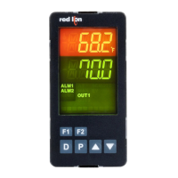
Analog Output) to maintain a process at a determined setpoint value. Dual
4-digit display readings allow viewing of the temperature/process and setpoint
value simultaneously. Front panel indicators inform the operator of alarm and
control output status. Comprehensive programming features allow this controller
to meet a wide variety of application requirements.
MAIN CONTROL
The PXU allows the user to select between PID, On/Off and Manual control
mode. The PXU has the ability to provide 2 control outputs. The control outputs
can be individually configured for Reverse or Direct (heating or cooling)
applications. The PID tuning constants can be established via on-demand auto-
tune. The PID constants can also be programmed, or fine-tuned, through the
front panel or a PC and then locked out from further modification.
ALARMS
Alarm(s) can be configured independently for absolute high or low acting
with balanced or unbalanced hysteresis. They can also be configured for
deviation and band alarm. In these modes, the alarm trigger values track the
setpoint value. Adjustable alarm hysteresis can be used for delaying output
response. The alarms can be programmed for Automatic or Latching operation.
A selectable standby feature suppresses the alarm during power-up until the
temperature stabilizes outside the alarm region.
CONSTRUCTION
The PXU is constructed of a lightweight, high impact, black plastic textured
case with a clear display window. Modern surface-mount technology, extensive
testing, plus high immunity to noise interference makes the controller extremely
reliable in industrial environments.
SAFETY SUMMARY
All safety related regulations, local codes and instructions that appear in the
manual or on equipment must be observed to ensure personal safety and to
prevent damage to either the instrument or equipment connected to it. If
equipment is used in a manner not specified by the manufacturer, the protection
provided by the equipment may be impaired.
Do not use this unit to directly command motors, valves, or other actuators not
equipped with safeguards. To do so can be potentially harmful to persons or
equipment in the event of a fault to the controller. If redundant safeguards are not
in place, an independent and redundant temperature limit indicator with alarm
outputs is strongly recommended.
z PID CONTROL
z ACCEPTS TC and RTD
z ACCEPTS 0-10 V, 0/4-20 mA or 0-50 mV SIGNALS
z FUNCTIONS AS A DIGITAL POT
z ON DEMAND AUTO-TUNING OF PID SETTINGS
z DC ANALOG CONTROL OUTPUT (OPTIONAL)
z 2 USER PROGRAMMABLE FUNCTION BUTTONS
z PC (MODELS WITH RS 485) OR FRONT PANEL PROGRAMMING
z 1/16, 1/8 or 1/4 DIN
z CONTROLLERS MEET IP65 REQUIREMENTS
Bulletin No. PXU-D
Drawing No. LP0932
Released 09/15
C
US LISTED
U
L
R
13RW
PROCESS CONTROL EQUIPMENT
(48.0)
1.89
1.89
(48.0)
(45.0)
1.77
1.77
(45.0)
6
5
4
3
2
1
12
11
10
9
8
7
15
14
13
16
17
18
0.26
(6.70)
3.14 (79.70)
0.31
(7.80)
0.47 (11.88)
0.83 (21.0)
DIMENSIONS In inches (mm) - 1/16 DIN
PANEL CUT-OUT
CAUTION: Risk of electric shock.
When the power is on, DO NOT touch the AC terminals, an electric shock may
occur. Make sure the power is disconnected when you check the input power
supply.
1. Prevent dust or metallic debris from falling into the controller and causing malfunctions. DO
NOT modify the controller.
2. The PXU is an open-type device. Make sure it is installed in an enclosure free of dust and
humidity in case of an electric shock.
3. Wait for one minute after the power is switched off to allow the unit to discharge. DO NOT
touch the internal wiring within this period of time.
CAUTION: Risk of Danger.
Read complete instructions prior to
installation and operation of the unit.

Other manuals for red lion PXU

Questions and Answers:

red lion PXU Specifications

General IconGeneral
Control ModesPID, On/Off
MountingPanel Mount
Input TypesThermocouple, RTD
Output TypesRelay, Analog
Power Supply100-240 VAC, 24 VAC/VDC
CommunicationModbus RTU

Summary

MODEL PXU - TEMPERATURE/PROCESS CONTROLLERS

GENERAL DESCRIPTION

Provides an overview of the PXU controller's capabilities and features.

MAIN CONTROL

Details the controller's main control modes, outputs, and tuning.

ALARMS

Explains the configuration options for alarm functions.

CONSTRUCTION

Describes the physical build and materials of the controller.

DIMENSIONS IN INCHES (MM) - 1/16 DIN

DIMENSIONS IN INCHES (MM) - 1/8 DIN

DIMENSIONS IN INCHES (MM) - 1/4 DIN

GENERAL SPECIFICATIONS

RTD INPUTS

Details specifications for RTD sensor types.

PROCESS INPUTS

Provides specifications for various process signals.

THERMOCOUPLE INPUTS

Details specifications for thermocouple sensor types.

ORDERING INFORMATION

ACCESSORIES

Lists optional accessories available for the controller.

EMC INSTALLATION GUIDELINES

SETTING THE CURRENT INPUT JUMPER

Procedure to configure the input jumper for current inputs.

INSTALLING THE CONTROLLER

1/16 DIN INSTALLATION

Instructions for mounting the 1/16 DIN controller model.

1/8 DIN INSTALLATION

Instructions for mounting the 1/8 DIN controller model.

1/4 DIN INSTALLATION

Instructions for mounting the 1/4 DIN controller model.

WIRING THE CONTROLLER

CONTROLLER POWER CONNECTIONS

Details on wiring the controller's power supply.

INPUT CONNECTIONS

Wiring guidance for various sensor and process inputs.

CONTROL AND ALARM OUTPUT CONNECTIONS

Wiring for output control signals and alarm outputs.

REVIEWING THE FRONT KEYS AND DISPLAY

FRONT PANEL KEYS

Description of the functions of the front panel keys.

PROGRAMMING LOOPS

DISPLAY LOOP

Describes the main display navigation and parameter viewing.

PARAMETER LOOP

Explains navigation through configurable parameters.

HIDDEN LOOP

Describes access to advanced and hidden parameters.

PROGRAMMING LOOPS

ACCESS CODE

Details on managing access to programming features via an access code.

DISPLAY/PARAMETER/HIDDEN LOOP PARAMETER DESCRIPTIONS

ACTIVE SETPOINT VALUE

Description of the SPx parameter for active setpoint value.

OUTPUT POWER OFFSET

Description of the OP0F parameter for output power offset.

PROPORTIONAL BAND

Description of the Prop parameter for proportional band.

MODULE 1 - INPUT PARAMETERS (1- IN)

INPUT TYPE

Selection of the input sensor type.

TEMPERATURE SCALE

Setting the temperature scale to Fahrenheit or Celsius.

DIGITAL FILTERING

Configuration of the digital filter for noise reduction.

DISPLAY VALUE SCALING

Scaling input signal to display units.

SETPOINT LIMITS

COLD JUNCTION COMPENSATION

USER INPUT FUNCTION

F1 / F2 KEY FUNCTION

SETPOINT HIGH LIMIT

ALARM 1 ACTION

ALARM 2 ACTION

ALARM 3 ACTION

ALARM HYSTERESIS

MODULE 2 - OUTPUT PARAMETERS (2-0P)

CONTROL ACTION

Defines the heating/cooling direction for outputs.

CONTROL MODE

Selection of PID, On/Off, or Manual control modes.

OUTPUT 1 CYCLE TIME

Setting the timing for time proportional output 1.

OUTPUT 1 ANALOG SCALING

Scaling analog output signals for output 1.

OUTPUT 2 POWER LIMITS

RELATIVE GAIN

DEAD BAND/OVERLAP

ON/OFF CONTROL HYSTERESIS

MODULE 3 - LOCKOUT PARAMETERS (3-LC)

SETPOINT ACCESS

Configuration of setpoint parameter visibility.

PID ACCESS

Configuration of PID parameter visibility.

ALARM ACCESS

Configuration of alarm parameter visibility.

ACCESS CODE

Setting the security code for parameter access.

MODULE 4 - ALARM PARAMETERS (4-AL)

ALARM 1 ACTION

Defining the action for Alarm 1.

ALARM 2 ACTION

Defining the action for Alarm 2.

ALARM 3 ACTION

Defining the action for Alarm 3.

ALARM HYSTERESIS

Setting the hysteresis value for alarms.

SERIAL COMMUNICATIONS

PXU FREQUENTLY USED MODBUS REGISTERS

Common Modbus register mappings for PXU controller.

TROUBLESHOOTING

CONTROL MODE EXPLANATIONS

ON/OFF CONTROL

Explanation of On/Off control logic and figures.

PID CONTROL

Explanation of PID control logic and response.

PID TUNING EXPLANATIONS

AUTO-TUNE

Procedure for automatic PID tuning.

START AUTO-TUNE

Steps to initiate the auto-tune process.

PID ADJUSTMENTS

PROCESS RESPONSE EXTREMES

Analyzing process response for PID tuning.

MANUAL TUNING

Procedure for manual PID tuning.

DIGITAL POTENTIOMETER

Using the controller as a digital potentiometer.

Related product manuals