14
OP1 CYCLE TIME
. to . seconds
OP2 CYCLE TIME
. to . seconds
The Cycle Time is entered in seconds with one tenth of a second resolution.
It is the total time for one on and one off period of an OP1 time proportioning
control output. With time proportional control, the percentage of power is
converted into an output on-time relative to the cycle time value set. (If the
controller calculates that 65% power is required and a cycle time of 10.0
seconds is set, the output will be on for 6.5 seconds and off for 3.5 seconds.)
For best control, a cycle time equal to one-tenth or less, of the natural period of
oscillation of the process is recommended. When OP1 is an analog output, the
Cycle Time is the analog output update time. A Cycle Time selection of 0.0 will
disable the output.
CONTROL ACTION
r = Reverse Acting
d = Direct Acting
A = Alarm 3
This determines the action for each Output. When programmed as r1d2,
Output 1 will function in the Reverse mode (heating) and Output 2 will function
in the Direct mode (Cooling). When selected as A, OP2 is configured as the
alarm 3 output and the alarm 3 settings will become accessible in the Alarm
module configuration menu and OP2 parameters will no longer be available.
OUTPUT 1 POWER LOWER LIMIT
. to . %
This parameter may be used to limit controller power at the lower end due to
process disturbances or setpoint changes. Enter the safe output 1 power limit for
the process. When the controller is in USEr or OnOF Control Mode or Auto Tune,
this limit does not apply.
OUTPUT 1 POWER UPPER LIMIT
. to . %
This parameter may be used to limit controller power at the upper end due to
process disturbances or setpoint changes. Enter the safe output 1 power limit for
the process. When the controller is in USEr or OnOF Control Mode, this limit
does not apply.
INPUT FAIL OP1 POWER LEVEL
This parameter sets the power level in the event of an input failure (open TC/
RTD or shorted RTD). Manual (USEr) Control overrides the input fail preset.
The Cycle Time is entered in seconds with one tenth of a second resolution.
It is the total time for one on and one off period of an OP2 time proportioning
control output. With time proportional control, the percentage of power is
converted into an output on-time relative to the cycle time value set. (If the
controller calculates that 65% power is required and a cycle time of 10.0
seconds is set, the output will be on for 6.5 seconds and off for 3.5 seconds.)
For best control, a cycle time equal to one-tenth or less, of the natural period of
oscillation of the process is recommended. When OP2 is an analog output, the
Cycle Time is the analog output update time. A Cycle Time selection of 0.0 will
disable the output.
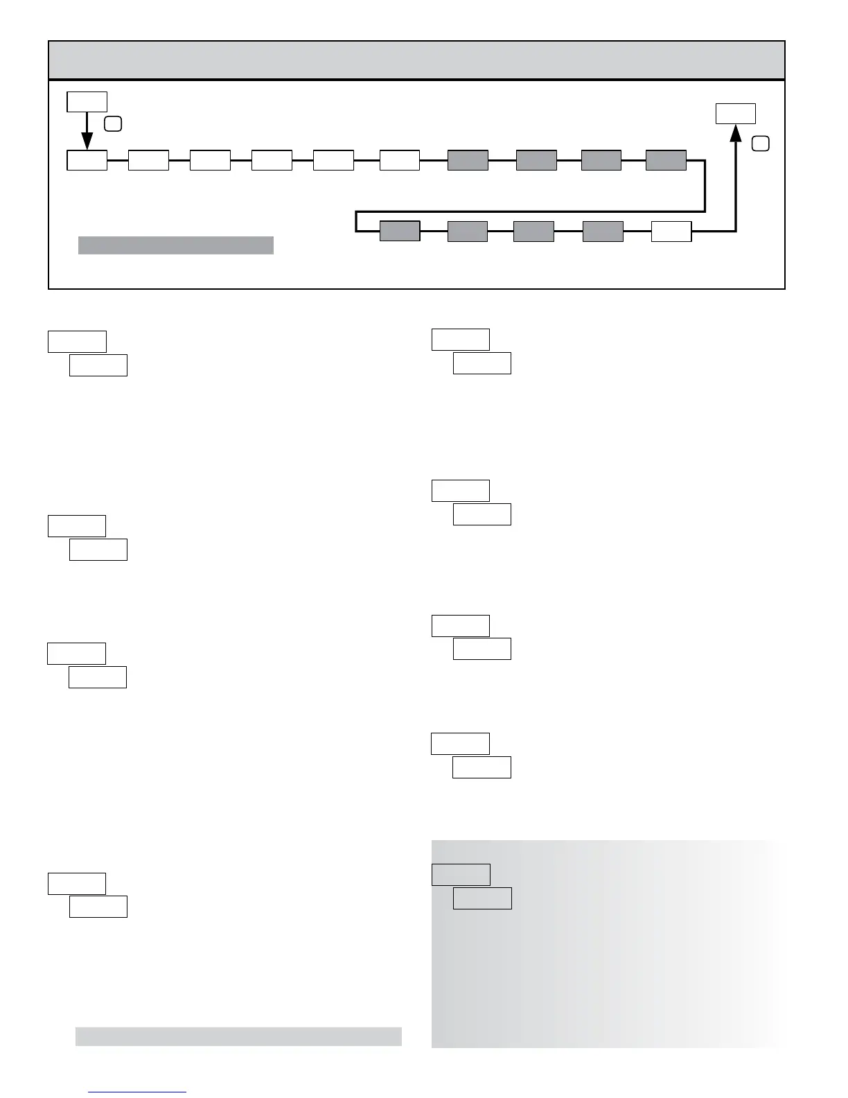
7.2 mOdule 2 - OuTpuT parameTers (2-OP)
OP1 CYCLE
TIME
CONTROL
ACTION
CONTROL
MODE
OUTPUT 1
POWER ANALOG LOW
SCALING
OUTPUT 1
INPUT
FAIL OP1
ANALOG
HIGH SCALING
OUTPUT 1
TIME
OP2 CYCLE
LOW LIMITHIGH LIMIT
POWER
OUTPUT 1
POWER LEVEL
OUTPUT 2
POWER
LOW LIMIT
P
P
ON/OFF
CONTROL
INPUT
FAIL OP2
POWER LEVEL
OUTPUT 2
DEADBAND
RELATIVE
GAIN
OUTPUT 2
HYSTERESIS
POWER
HIGH LIMIT
OUTPUT 2
Programming/model dependent.
PARAMETER MENU
. to . %
CONTROL MODE
Select the Control Output(s) mode of operation. This parameter can also be
selected in the Hidden Loop when configured in Module 3.
l
C
I
I
C
.
CC
.
.
.
I
.
CC
OUTPUT 1 ANALOG LOW SCALING
The output power level that corresponds with 0 V or 4 mA analog output.
. to .
.
OUTPUT 1 ANALOG HIGH SCALING
The output power level that corresponds with 10 V or 20 mA analog output.
An inverse action can be achieved by reversing the high and low scaling points.
. to .
.
Shaded parameters are programming/model dependent.
 Loading...

