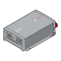
The REDARC RS Series 12 V Inverters are designed to convert DC power from a battery into pure sine wave AC power, suitable for a wide range of applications. These inverters provide an output that is often superior to standard mains supply, making them ideal for both residential and industrial use, depending on the specific model. The R-12-1000RS-NA and R-12-1500RS-NA models are suitable for residential and industrial applications, while the R-12-2000RS-NA and R-12-3000RS-NA models are exclusively for industrial applications.
Safety and Installation Guidelines
Before operating the inverter, it is crucial to read and understand the entire manual, and ensure the inverter is installed according to the provided instructions. REDARC strongly recommends that installation be performed by a suitably qualified person.
WARNING: Risk of Electrical Shock and Fire
- Do not disassemble the inverter: The internal circuitry contains hazardous voltages. Attempting to service the unit yourself can result in electric shock or fire and will void the warranty.
- Avoid exposure to elements: Do not expose the inverter to rain, snow, spray, bilge, or dust, as this can damage the inverter or other connected appliances, and may lead to electric shock or fire.
- Ensure proper grounding: Operating the inverter without a proper and reliable ground connection can create an electrical safety hazard. Ensure the ground connection is made during installation and maintained. For fixed and transportable (vehicle) installations, follow appropriate codes and standards for your region. A broken grounding path puts the user at risk of shock or electrocution.
- Qualified electrical work: All electrical work must comply with local and national codes, standards, and wiring rules. Installation must be performed by qualified personnel who meet all local and governmental code requirements for licensing and training in electrical power systems. Safety regulations relevant to the installation and use location must be followed during installation, operation, and maintenance. Improper operation carries risks of electric shock, fire, or damage to equipment and property.
- Cable and fuse sizing: Ensure ground, AC, and DC cable sizes conform to local and national standards and wiring codes to prevent fire hazards.
- Disconnect power before wiring: Before proceeding with any wiring, carefully check that the inverter is not connected to any batteries and that all wiring is disconnected from any electrical sources to prevent electric shock and fire.
- Internal heat-sinks: When removing the cover for servicing, be aware that internal heat-sinks are not bonded to ground; test before touching.
- Do not back-feed AC: Never connect the output terminals of the inverter to an incoming AC source.
CAUTION:
- Supervision for users: This appliance is not intended for use by persons (including children) with reduced physical, sensory, or mental capabilities, or lack of experience and knowledge, unless they are supervised or have been instructed on how to use the appliance by a person responsible for their safety. Children should be supervised to ensure they do not play with the appliance.
- Wiring integrity: Do not operate the inverter with damaged or substandard wiring. Incorrect cable or fuse sizing can harm the installer or user, and damage the inverter or other appliances. The installer is responsible for ensuring correct cable and fuse sizes. Refer to Section 2.2.4 (page 19) for detailed information.
- Tight DC connections: Ensure all DC connections are tight, torqued between 9 to 10 ft lbf (11.7 to 13 Nm). Loose connections can cause overheating and potential hazards.
- Flammable materials: Some inverter components can cause arcs and sparks. Do not place batteries, flammable materials, or anything requiring ignition protection around the inverter, as this may lead to fire or explosion. Exercise caution to avoid dropping metal tools onto vehicle batteries, which can cause sparks, short-circuit the battery, or damage other electrical parts, potentially leading to an explosion.
- Personal metal items: Remove rings, bracelets, necklaces, and watches when working with a battery. A battery can produce high short-circuit currents capable of welding metal items, causing severe burns.
- Battery acid contact: If battery acid contacts skin or clothing, remove affected clothing and wash the area immediately with soap and water. If acid enters the eye, flood the eye with running cold water for at least 10 minutes and seek immediate medical assistance.
- No smoking near batteries: NEVER smoke or allow sparks or flames near a battery, as this may cause it to explode.
- Battery fusing: Batteries can provide very large currents in a short circuit. A fuse must be installed on the positive supply cable as close to the battery as practical. Failure to do so provides inadequate protection against fire in a short circuit. Use only high-quality copper cable and keep cable length short. Refer to Section 2.2.4 (page 19) for more information.
NOTICE:
- Inspect upon receipt: Examine the box for damage upon receipt. If damage is found, notify the company from which the unit was purchased.
- Ventilation: Install the inverter in a well-ventilated area with reasonable clearance. Do not install it in a zero-clearance compartment or obstruct ventilation openings, as this can lead to overheating and permanent damage.
- Reverse polarity: Reverse polarity connection will blow the internal fuse and may permanently damage the inverter, voiding the warranty.
- Avoid back-feeding appliances: Do not operate appliances that may feed power back into the inverter, as this can cause damage.
- Frequency matching: Ensure the inverter's frequency output matches the requirements of all connected appliances. Using appliances that require a different AC frequency can damage them. Output AC frequency is dip switch selectable (see Section 2.1.3, page 14).
- Indoor use only: All RS Series Inverters are suitable for indoor use only.
- Fan airflow: The direction of fan airflow must be horizontal.
Front Panel Operation
The front panel features several controls and indicators for easy operation:
- Main Switch (1): This 3-stage switch controls the AC mains output (ON, OFF, or Remote mode). When set to ON (either the first or second position), the LEDs will glow GREEN. The second ON position is specifically for operating the inverter via the REMOTE-RS inverter remote. Setting the switch to OFF stops the inverter and turns off the LEDs.
- Indicator LED (2): This LED provides visual feedback on the inverter's status, including input voltage level and output load level.
- Input Voltage Level:
- Red: < 11.0 V
- Orange: 11.0 ~ 11.5 V
- Green: 11.5 ~ 15.0 V
- Orange: 15.0 ~ 15.5 V
- Red: > 15.5 V
- Output Load Level (for 12 V Models):
- 1000 W: Green (0 ~ 1000 W), Orange (1000 ~ 1150 W), Red (> 1150 W)
- 1500 W: Green (0 ~ 1500 W), Orange (1500 ~ 1725 W), Red (> 1725 W)
- 2000 W: Green (0 ~ 2000 W), Orange (2000 ~ 2300 W), Red (> 2300 W)
- 3000 W: Green (0 ~ 3000 W), Orange (3000 ~ 3450 W), Red (> 3450 W)
- Function Switch (3): This switch allows selection of output voltage, frequency, and power saving mode using dip switches.
- Output Voltage Selection (Switches 1 and 2):
- 100 V: Switch 1 OFF, Switch 2 OFF
- 110 V: Switch 1 ON, Switch 2 OFF
- 115 V: Switch 1 OFF, Switch 2 ON
- 120 V: Switch 1 ON, Switch 2 ON
- Output Frequency (Switch 3):
- 50 Hz: Switch 3 OFF
- 60 Hz: Switch 3 ON
- Power Saving Mode Select (Switch 4):
- Power Saving OFF: Switch 4 OFF
- Power Saving ON: Switch 4 ON
- Power Saving Load Adjustment (4): A potentiometer allows users to adjust the input sleep and wake-up thresholds based on the applied load.
- Minimum (potentiometer fully anti-clockwise):
- 1000/1500/2000 W: Sleep Power < 20 W, Wake Up Power > 40 W
- 3000 W: Sleep Power < 40 W, Wake Up Power > 60 W
- Maximum (potentiometer fully clockwise):
- 1000/1500/2000 W: Sleep Power < 110 W, Wake Up Power > 160 W
- 3000 W: Sleep Power < 240 W, Wake Up Power > 280 W
- TRC Port (RJ45) (5): Not currently used.
- AC Output Interface (6): Provides the AC output connection. For 1000/1500/2000 W models, this is an AC output socket. For 3000 W models, it consists of AC output terminals for hardwiring.
Inverter Status and Fault Conditions:
The LED status provides crucial information for troubleshooting:
- Power On / Normal: Green LED.
- Over Current / Over Load (AC output short and overload): Red LED. Remedy: Reduce load. If it doesn't recover, cycle the power switch.
- Over Voltage Protection (Input DC voltage over spec): Red LED (all segments). Recovery Points: 14.5 V (12 V Models). Remedy: Check input voltage and reduce it to meet specifications.
- Under Voltage Protection (Input DC voltage under spec): Red LED (some segments). Recovery Points: 12.5 V (12 V Models). Remedy: Check input voltage, recharge battery, and verify all input connections and cables. If conditions are within spec, cycle the power switch.
- Device Startup process abnormal: Orange LED.
- Under Temperature (Heatsink temp. under -4°F (-20°C)): Orange LED (all segments). Recovery point: > 32°F (0°C). Remedy: Reduce load. If it doesn't recover, cycle the power switch.
- Over Temperature (Heatsink temp. over 176°F (80°C)): Orange LED (some segments). Recovery point: < 60°F (140°C). Remedy: Improve ventilation, ensure openings are not obstructed, and reduce ambient temperature.
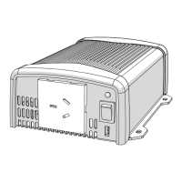
Rear Panel Operation
The rear panel includes connections for remote control and DC input:
- Remote Port (RJ11) (1): Allows connection to REMOTE-RS remote controls via RS-232 communication. To enable, set the main switch on the inverter to the REMOTE position.
- Remote Control Green Terminal (2): Connected to a Form C relay for fault indication. The relay switches when a fault occurs, such as input under/over voltage, output short-circuit/overload, or under/over temperature.
- Chassis Ground (3): Use 16 AWG (1.5 mm²) or thicker cable to connect to the vehicle earth or chassis ground. This connection must be made before any other connections to the inverter.
- DC Input Connector (4): For connecting the supply battery.
Installation
- Mounting: Install the inverter in a well-ventilated area with adequate clearance. Avoid zero-clearance compartments or obstructing ventilation openings to prevent overheating.
- Ensure the inverter is dry and protected from moisture.
- Ambient temperature should be between 32°F (0°C) and 104°F (40°C).
- Avoid installing near fuel storage areas or engine compartments due to potential arcs and sparks.
- Ensure at least 1" (25 mm) clearance from surrounding objects for ventilation.
- Do not install in dusty environments where dust can enter the unit and interfere with fan operation.
- A fuse must be fitted between the battery and the inverter, positioned as close to the battery as possible.
- Do not mount where it will be exposed to gases produced by the battery, as these gases are corrosive and can damage the inverter.
- Ventilation Fan: The fan is load and temperature controlled. It will operate when AC power is consumed. Ensure ventilation openings are not obstructed and maintain at least 1" (25 mm) clearance.
- Safety Before Installing DC Wiring Connections:
- Loads Disconnected: Ensure all loads are disconnected from the AC output and the inverter main switch is OFF before connecting DC cables.
- Cable and Fuse Size: Use suitably rated cables and fuses. Refer to Section 2.2.4 (page 19) for recommended sizes. Using underrated cables or an oversized fuse can cause harm or damage.
- Chassis Ground Connection: Connect the Chassis Ground Terminal to the vehicle's ground (for negative ground vehicles) before any other connections.
- DC Wiring Connections:
- Remove bolts and washers from input terminals.
- Insert crimped/terminated DC cable lugs into input terminals, ensuring positive (+) cable goes to positive terminal and negative (-) cable to negative terminal.
- Screw bolts and washers tightly.
- Connect DC cables to the appropriate battery supply or other DC power source, ensuring correct polarity.
- AC Safety Grounding: All wiring, including grounding, must be performed by a qualified person and comply with local and government code requirements.
- Turning The Inverter On:
- Once DC cables and Chassis Ground are correctly installed, turn the power switch to the single line ON position. The second ON switch position is only for remote control via the REMOTE-RS inverter remote.
- All LEDs should illuminate green when the inverter is switched on. If not, refer to Section 2.1.2 (page 12) for troubleshooting.
- Connecting AC: If all LEDs are green, switch the unit OFF, then plug AC cord(s) into the GFCI socket(s) and connect loads to the inverter AC output. Then, turn the inverter switch to ON.
Maintenance
- Cleaning: Turn the unit OFF before cleaning.
- Exterior: Clean the exterior periodically with a damp cloth to prevent dust and dirt accumulation.
- DC Input Terminals: Tighten the screws on the DC input terminals.
- Ventilation: Use a vacuum cleaner to remove dust from ventilation openings and the fan area.