24
3 INSTALLATION
CAUTION
ENSURE THAT ALL THE DC CONNECTIONS ARE TIGHT - TORQUE TO 1.5 FT-LBF (2.8 NM). LOOSE CONNECTIONS
COULD RESULT IN OVERHEATING AND CAN BE A POTENTIAL HAZARD.
DO NOT OPERATE THE INVERTER WITH DAMAGED OR SUBSTANDARD WIRING. SELECTING THE WRONG CABLE OR
FUSE SIZE COULD RESULT IN HARM TO THE INSTALLER OR USER AND/OR DAMAGE TO THE INVERTER OR OTHER
APPLIANCES INSTALLED IN THE SYSTEM. THE INSTALLER IS RESPONSIBLE FOR ENSURING THAT THE CORRECT
CABLE AND FUSE SIZES ARE USED WHEN INSTALLING THIS INVERTER. REFER TO SECTION 2.2.4 (PAGE 10) FOR
MORE INFORMATION.
3.6 AC Safety Grounding
NOTICE
The R-12-1000RS-NA, R-12-1500RS-NA and R-12-2000RS-NA are fitted with a GFCI and is UL 458
compliant whereas the R-12-3000RS-NA is required to have a UL compliant GFCI added to be compliant
with UL 458, refer to Section 2.1.6 (page 16) for more information.
All wiring, including grounding, must be performed by a suitably qualified person and must comply with
all local and government code requirements that are application to the installation location and type.
3.7 Turning The Inverter On
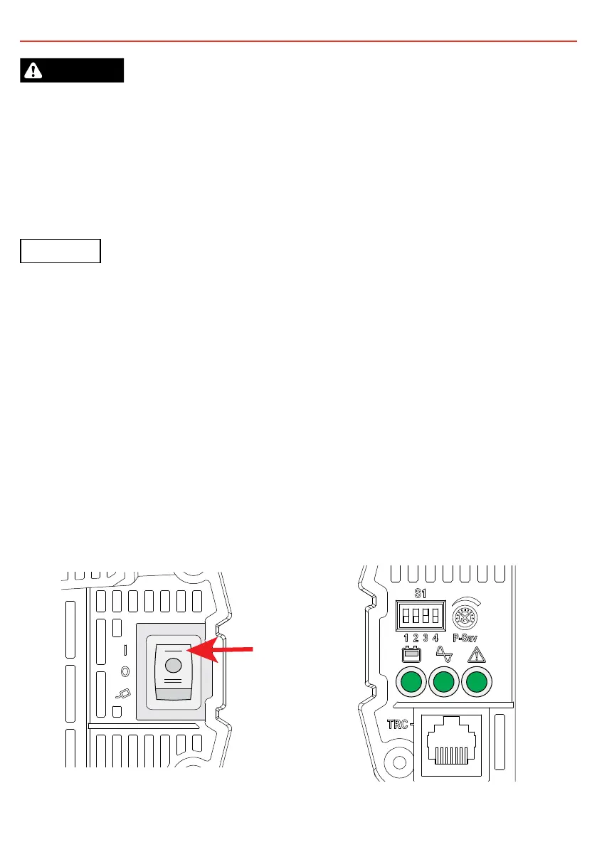
3.7.1 Switch Controls
With the DC cables and Chassis Ground point correctly installed the power switch on the inverter can be
turned ON to the single line side. The second ON switch is to be used ONLY when controlling the inverter
through the REMOTE-RS inverter remote.
3.7.2 LEDs and Possible Issues
All LEDs will illuminate green once switching the inverter on. If the inverter status is not green refer to
Section 2.1.2 (page 12).
FIGURE 3.7.1: Switching Inverter ON FIGURE 3.7.2: Correct Inverter Status
 Loading...