3
CONTENTS
Table of Contents Page
1 - Specifications 3
2 - Installation 5
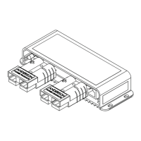
2.1 - Mounting the main unit 5
2.2 - Wiring the brake controller 6
2.2.1 Red Wire (Vehicle Brake light) Connection 7
2.2.2 Wiring Diagrams - Electric Brakes 8
2.2.3 Wiring Diagrams - Electric / Hydraulic Brakes 9
2.2.4 Wiring Diagrams - Vehicles with CAN Bus System 10
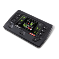
2.3 - Mounting the Remote Head 11
2.4 - Installation Accessories 11
2.5 - Universal Switch Panel Insert 11
2.6 - Mounting the remote head on a dash or console panel 12
2.7 - Active Calibration 13
3 - Operation 14
3.1 - Adjusting the Braking Force 14
3.2 - Manual Override 14
3.3 - Operating Modes 15
3.3.1 - Proportional Mode (Blue LED) 15
3.3.2 - User Controller Mode (Green LED) 15
3.3.3 - Changing Modes 16
3.4 - Park Brake Feature 16
3.5 - Visual User Guide 17
3.6 - LED Indication 18
3.7 - Troubleshooting 18
4 - Periodic Maintenance / Checks 21
5 - Frequently Asked Questions 22
6 - Wiring Gauge Guide 23
7 - Checking the Product Serial Number 23
8 - FCC Declaration 24
9 - Notes 25
10 - Two Year Product Warranty 26
1 SPECIFICATIONS
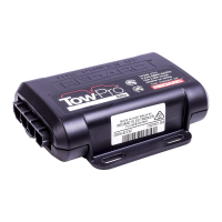
Part Number EBRH-ACCV3-NA
Operating Voltage 9V - 32V
Nominal Input System Voltage 12V 24V
Brake Input Signal Voltage OFF: 0V
ON: +12V nominal
OFF: 0V
ON: +24V nominal
Brake Coil Voltage 12V 12V
Max. Trailer Axles 3 Axles 3 Axles
Nominal Current Draw 18A 18A
Max. Rated Current 25A 30A
Standby Current <5mA
Operating Temp -4 °F to 140 °F (-20°C to +60°C)
Weight 7.05 oz (200g)
Warranty 2 years
 Loading...