RD-2-7783 (REV. A) Page 4 SUBJECT TO CHANGE WITHOUT NOTICE
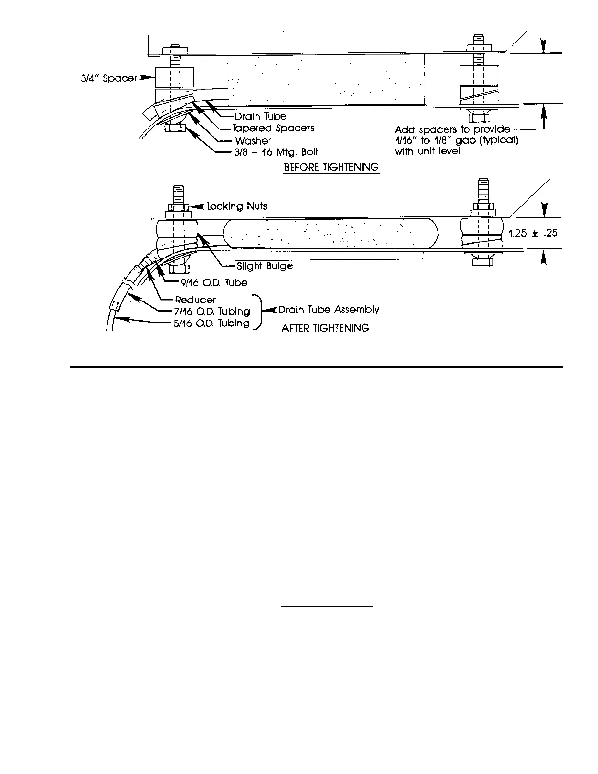
Figure 2
B. Drain Hose Installation
Note: The drain hose is stepped down in size at two places to promote siphoning water from the drain pan under
evaporator. The reduction in diameter forces the water to flow in a solid column. This creates a suction that draws the rest of
the water out of the pan. For this effect to work properly, the last two feet of 5/16 O.D. drain tube should point straight down
or as close to this as possible.
1. Locate small end of drain tube (5/16 O.D.) so that it exits at desired location. Make sure that it points downhill and
secure with clamps or tie wraps. Do not crush the tube or cut off the 5/16 O.D. tubing.
2. Route the drain tube to the unit so that it travels in a downward direction from the unit.
3. Cut off the 7/16 O.D. tube to length and connect to reducer fitting on drain hose from unit. Secure drain tubes with tie
wraps. Attach to refrigerant hoses if they run downhill properly.
4. Inspect to make sure that drain tubes are not kinked, especially at back of cab and at drain pan within plenum.
C. Wiring
Note:
a. Unit is wired for negative ground.
b. Compressor Power and Ground Cables must be minimum 4GA.
c. Fused power source must be used or warranty may be voided.
1. Disconnect battery.
2. Route wire harness through 3/4" slot in plenum ring, then across inside of roof and down center or side post of windshield
to lower dash area.
3. Black Wires: Connect to suitable ground.
4. Red Wire (motor blower circuit): Connect to an ignition switch supply through a 15 amp circuit breaker (24V) or 30 amp circuit
breaker (12V).