Bulletin No. DA30D-A Effective 2018-11-02
Drawing No. LP1078
-4-
CONFIGURINGADA30D
The DA30D is configured using Crimson
®
3.1 software. Crimson is
available as a no charge download from Red Lion’s website. Crimson
updates for new features and drivers are posted on the website as they
become available. By configuring the DA30D using the latest Crimson
version, you are assured that your unit has the most up to date feature
set. Crimson software can configure the DA30D through the RS232 PGM
port, USB port, Ethernet port or SD card.
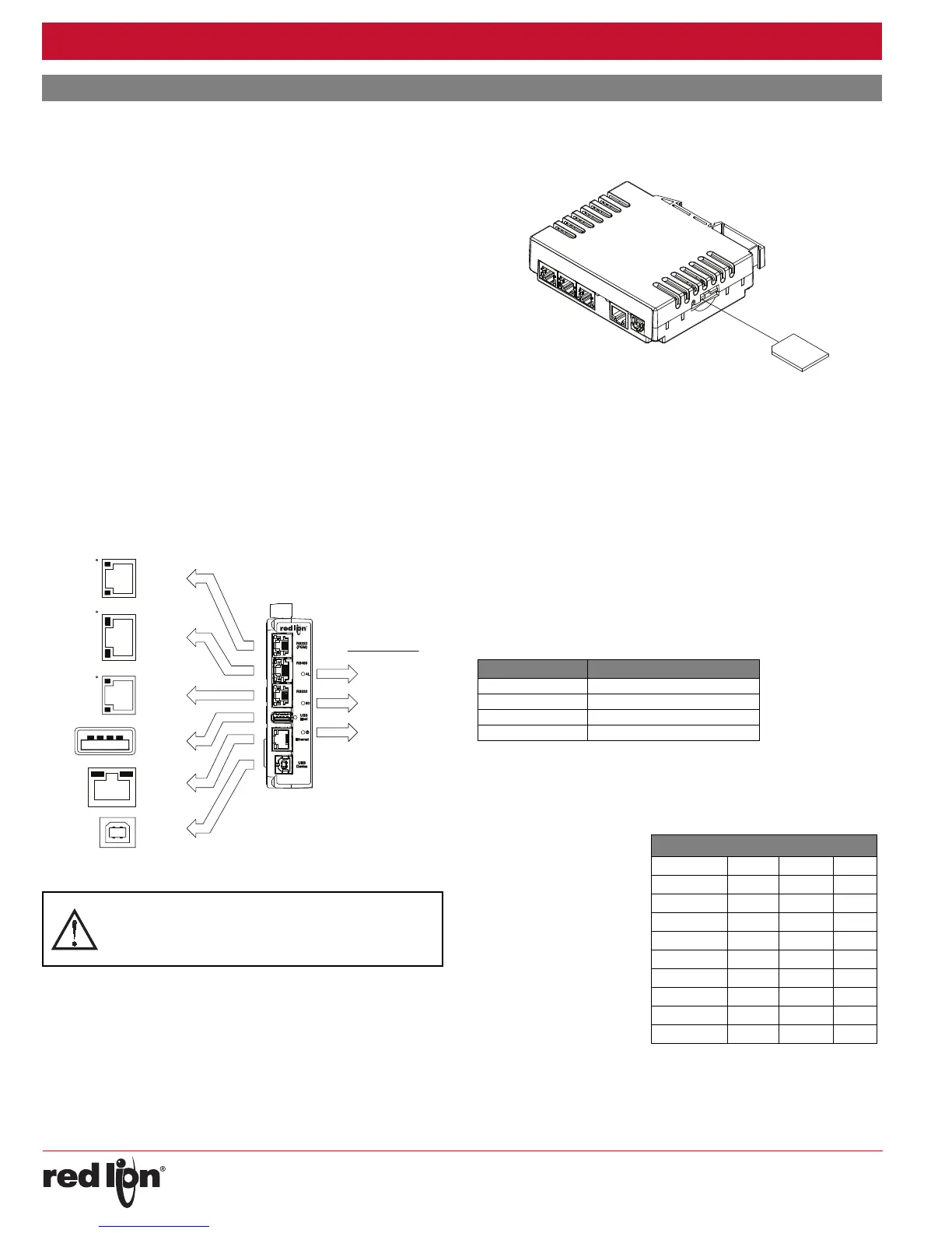
The DA30D has three serial ports, a USB device port, one USB Host
port, and an Ethernet port as shown below.
The serial ports are available via RJ connectors. There are two RS232
ports. The port labeled RS232 (PGM) can be used as a Programming
Port or you can assign a protocol to it. The RS485 port can be used for
both RS485 or 422 communications. All of the serial ports are isolated.
The Ethernet port can be programmed to communicate via ten
protocols simultaneously. For more information on protocol support,
please refer to the Crimson 3.1 User Manual.
The USB device port is a standard device port with a Type B connector,
and is used as the programming port. The driver needed to use the USB
port will be installed with
Crimson.
The USB host port is a standard host port with a Type A connector
and
can be used to interface to USB enabled peripherals. This port
supplies
5 V power per the USB standard.
The SD card can be used to program a DA30D by placing a database
image file on the SD card. The card is then inserted into the target DA30D
and powered. Refer to the Crimson 3.1 User Manual for more information
on the naming convention and location for this file.
USB,DATATRANSFERSFROMTHESDCARD
In order to transfer data from the SD card via the USB port, a driver
must be installed on your computer. This driver is installed with Crimson
and is located in the folder C:\Program Files\Red Lion Controls\Crimson
3.1\Device\ after Crimson is installed. This may have already been
accomplished if your DAx0D was configured using the USB port.
Once the driver is installed, connect the DAx0D to your PC with a USB
cable, and refer to the “Mounting the SD Card” section in the Crimson 3.1
User Manual.
INSERTION/REMOVALOFTHESDCARD
Insert the SD card into the slot provided with the card oriented as shown.
The card is inserted properly when the end of the card is flush with the
DA30D case. To remove the SD card, push in slightly on the card.
CABLESANDDRIVERS
Red Lion has a wide range of cables and drivers for use with many
different communication types. A list of these drivers and cables along
with pin outs is available from Red Lion’s website. New cables and
drivers are added on a regular basis. If making your own cable, refer to
the “Port Pin Outs” that corresponds to your specific model for wiring
information.
ETHERNETCOMMUNICATIONS
Ethernet communications can be established at either 10 BASE-T or
100 BASE-TX. The unit’s RJ45 jack is wired as a NIC (Network Interface
Card). It auto-detects remote transmit and receive pairs and correctly
assigns the transmit and receive pairs. This feature enables the user to
use whichever type of cable (cross-over or straight) is available.
The Ethernet connector contains two LEDs. A yellow LED in the upper
right, and a green LED in the upper left. The LEDs represent the following
statuses:
On the rear of each unit is a unique 12-digit MAC address. Refer to the
Crimson manual and Red Lion’s website for additional information on
Ethernet communications.
RS232PORTS
The DA30D has two
RS232 serial ports. Although
only one of these ports can
be used for programming,
both ports can be used for
communications with a PLC.
The serial ports can be used
for either master or slave
protocols with any DA30D
configuration. Each serial
port has a pair of LEDs to
indicate transmit and receive
activity. The pinouts are
shown to the right.
COMM
(PGM)
TxB (PIN 1)
TxA
RxB
RxA
TxEN
TxA (PIN 8)
TxB
COMM
RTS (PIN 6)
Tx
COMM
COMM
Tx
Rx
CTS (PIN 1)
RTS (PIN 6)
ETHERNET
(NIC)
TYPE B
USB
RS485/422
RS232
CTS (PIN 1)
COMM
Rx
RS232
USB
TYPE A
SD STATUS (BLUE)
POWER (GREEN)
ALARM (RED)
FRONT PANEL LEDS
WARNING - DO NOT CONNECT OR DISCONNECT CABLES
WHILE POWER IS APPLIED UNLESS AREA IS KNOWN TO BE
NON-HAZARDOUS. USB DEVICE PORT IS FOR SYSTEM SET-UP
AND DIAGNOSTICS AND IS NOT INTENDED FOR PERMANENT
CONNECTION.
LED COLOR DESCRIPTION
YELLOW solid Link established.
YELLOW flashing Data being transferred.
GREEN (OFF) 10 BASE-T Communications
GREEN (ON) 100 BASE-TX Communications
DAX0D RS232 TO A PC
DAx0D: RJ12 Name PC: DB9 Name
4COMM1DCD
5Tx2Rx
2Rx3Tx
N/C 4 DTR
3COMM5GND
N/C 6 DSR
1CTS7RTS
6RTS8CTS
N/C 9 RI
COMMUNICATINGWITHTHEDA30D
 Loading...