19
WARNING: TO AVOID SERIOUS INJURY, BEFORE PERFORMING ANY SER VICE OR AD JUST MENTS:
• Depress brake pedal fully and set parking brake.
• Place attachment clutch in “DISENGAGED” position.
• Turn ignition key to “STOP” and remove key.
• Make sure the blades and all moving parts have completely stopped.
• Disconnect spark plug wire from spark plug and place wire where it cannot come in contact with plug.
SERVICE AND ADJUSTMENTS
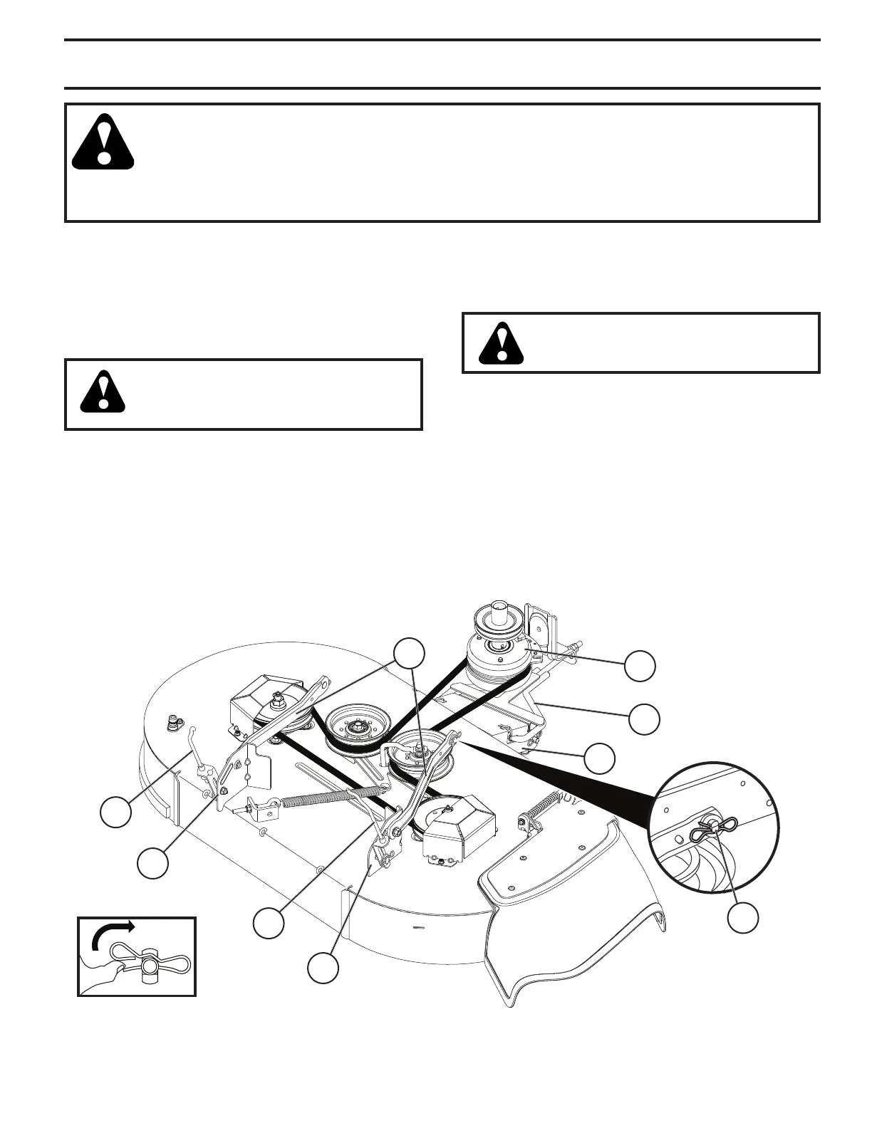
Fig. 22
TO REMOVE MOWER (See Fig. 22)
• Place attachment clutch in “DIS EN GAGED” position.
• Lower attachment lift lever to its lowest position.
• Remove mower belt from electric clutch pulley (M). See
Mower Drive Belt Removal in "TO REPLACE MOWER
BLADE DRIVE BELT" in this section.
CAUTION: After rear lift links are discon-
nected, the attachment lift lever will be
spring loaded. Have a tight grip on lift
lever when changing position of the lever.
• Go to either side of mower and disconnect mower
suspension arm (A) from chassis and rear lift link (C)
from rear mower bracket (D) - remove retainer springs
and washers.
• Go to other side of mower and disconnect the suspen-
sion arm and rear lift link.
• Disconnect front link (E) from front mower bracket (H).
• Slide mower out from under right side of tractor.
TO INSTALL MOWER (See Figs. 22 - 27)
Ensure tractor is on level surface and engage park ing brake.
• Lower attachment lift lever to its lowest position.
CAUTION: Lift lever is spring loaded.
Have a tight grip on lift lever, lower it
slowly and engage in lowest position.
NOTE: Ensure mower side suspension arms (A) are point-
ing forward before sliding mower under tractor.
• Slide mower under tractor until it is centered under
tractor.
• ATTACH MOWER SIDE SUSPENSION ARMS (A) TO
CHASSIS - Position hole in arm over pin (B) on outside
of tractor chassis and secure with retainer spring.
• Repeat on opposite side of tractor.
E
A
M
B
C
C
H
D
D