6
www.REEDINSTRUMENTS.com
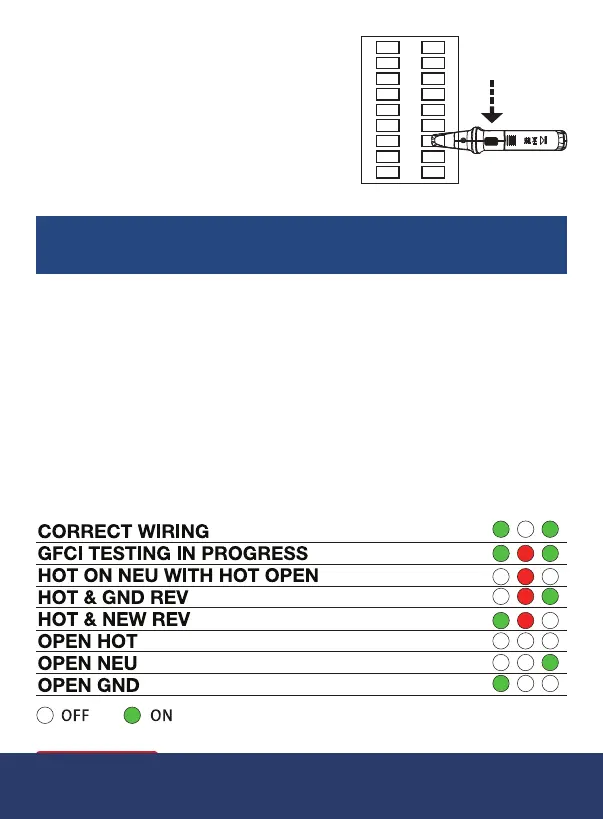
4. Atthebreakerbox,whilesetatthe
highest sensitivity, orient the receiver
as per the diagram to scan the
surface of the circuit breaker panel.
Move the receiver from top to bottom
on each side of the
breaker panel.
NOTE: Failure to orient the receiver as depicted may result in
faulty readings.
5. While moving the receiver, gradually reduce the sensitivity to pinpoint
theexactbreaker/fuseassociatedtothecircuitundertest.
Receptacle Wiring Test
1. Plug the transmitter into the receptacle.
2. Determine the status of the circuit connection according to the 3
LEDs.Thediagrambelowindicatesallofthepossiblecombinations
thatcouldappearforthecircuitundertest(GFCIbuttonsideofthe
transmitter)Ifobservedfromtheothersideduetothegroundhole
plugbeingontop,theorderofLEDindicatorlightswillbereversed.
Wiring Diagram
continued...
1.800.561.8187 info@REED-Direct.ca
REED-Direct.ca