Pantone 534 Blue
Pantone 123 Yellow
Pantone 485 Red
Pantone 123 Yellow
Pantone 534 Blue
Black
Rich Black -
20/20/20/100
Blue - 100/80/30/5
Yellow - 0/27/100/0
Red - 10/100/100/5
Yellow - 0/27/100/0
Blue - 100/80/30/5
Only if you REALLY need them:
Pantone 534 Blue - 100/80/30/5
Pantone 485 Red - 10/100/100/5
Pantone 123 Yellow - 0/27/100/
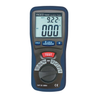
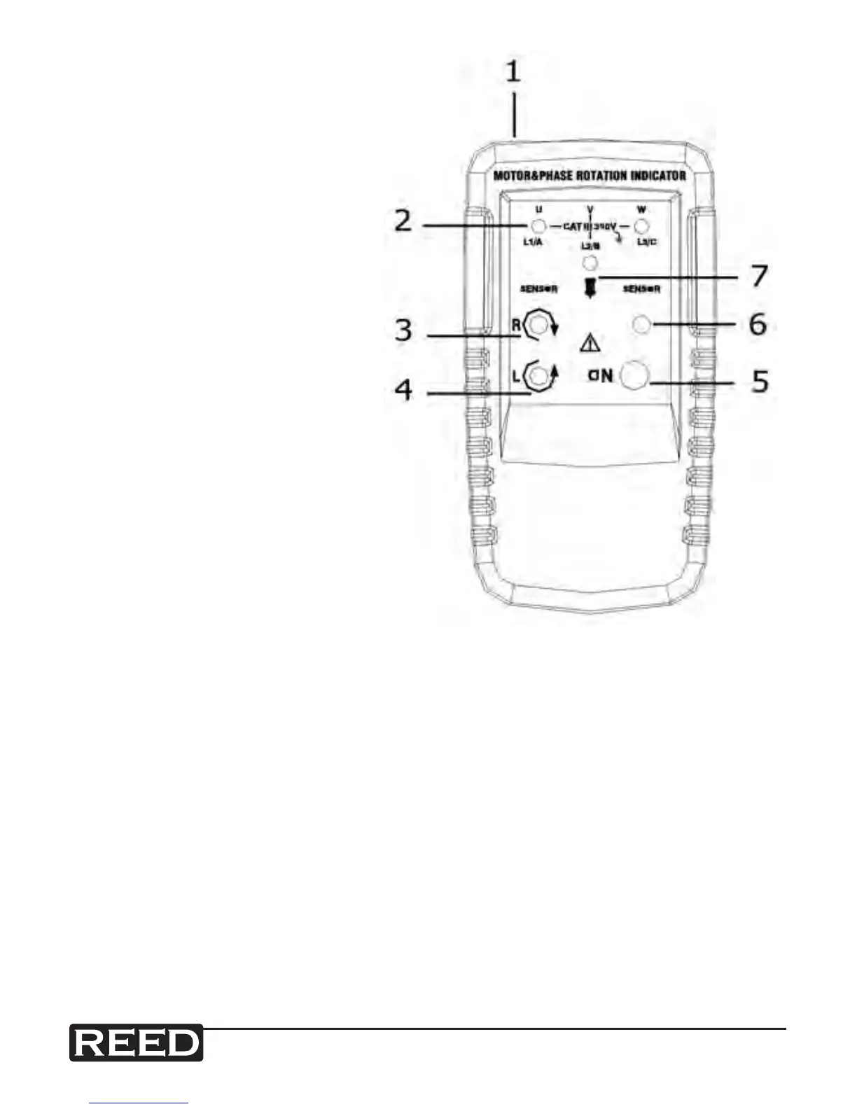
Instrument Description
1. Test lead input jack
2. L1, L2, L3 indicators
3. Clockwise rotation
LCD indicator
4. Counter-clockwise
rotation LCD indicator
5. ON/OFF button
6. ON/OFF indicator
7. Orientation symbol
Operating Instructions
Determining the Rotary Field Direction
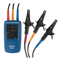
1. Connect one end of the test leads to the meter. Make sure the L1,
L2, and L3 test leads are connected to the corresponding input
jacks.
2. Connect the test probes to the other end of the test leads.
3. Connect the test probes to the three main phases. Press the ON/
OFF button. The green ON indicator shows that the instrument
is ready for testing. Either the Clockwise or Counter Clockwise
Rotary indicator will illuminate showing the type of rotary eld
direction present.
4. The rotary indicator will light up even if the neutral conductor, N,
is connected instead of the test lead input jack. See Phase
Indication Table for more information.
 Loading...