Pantone 534 Blue
Pantone 123 Yellow
Pantone 485 Red
Pantone 123 Yellow
Pantone 534 Blue
Black
Rich Black -
20/20/20/100
Blue - 100/80/30/5
Yellow - 0/27/100/0
Red - 10/100/100/5
Yellow - 0/27/100/0
Blue - 100/80/30/5
Only if you REALLY need them:
Pantone 534 Blue - 100/80/30/5
Pantone 485 Red - 10/100/100/5
Pantone 123 Yellow - 0/27/100/
Motor Test Requirements
See below for the minimum motor diameter and number of pole pair
needed to obtain a reliable test result.
• Number of pole pair
• Rotary number of rotary eld (1/min) at frequency (HZ)
• Angle between poles
• Minimum diameter of motor case
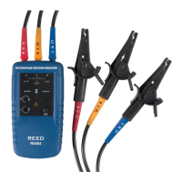
Determining the Motor Connection
1. Connect one end of the test leads to the unit. Make sure the L1,
L2, and L3 test leads are connected to the corresponding jack.
2. Connect the alligator clamps to the other end of the test leads.
3. Connect the alligator clamps to the motor connections, L1 to U,
L2 to V, L3 to W.
4. Press the ON/OFF button. The green ON indicator shows that the
instrument is ready for testing.
5. Turn the motor shaft half a revolution towards the right.
6. The bottom of this unit should be oriented towards the drive shaft.
Either the Clockwise or Counter Clockwise Rotary indicator will
illuminate showing the type of rotary eld direction present.
Magnetic Field Detection
To detect a magnetic eld, place this unit to a solenoid valve. A magnetic
eld is present if either the Clockwise or the Counter Clockwise Rotary
indicator illuminates.
 Loading...