14
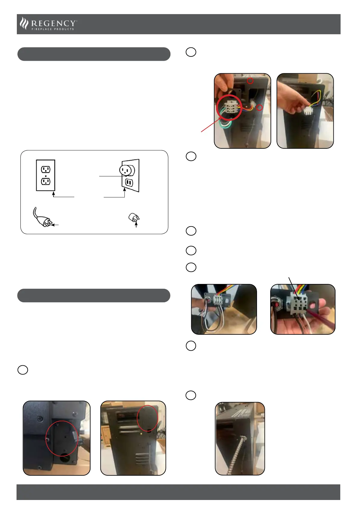
WIRING KITS
The appliance is supplied with a 3 prong plug with a 72" lead which
is included with the manual package, it will need to be modified for
hard wiring.
Note: Must be plugged into a 3 prong receptacle which is exposed
and accessible. Do not under any circumstances, cut the ground on
the 3 prong plug.
This appliance is for use on 120 Volts. Only the cord has a plug as
show in (A). An adapter as shown in (C) is available for connecting
three-blade grounding type plugs to two slot receptacles. The green
grounding lug extending from the adapter must be connected to
a permanent ground such as a properly grounded outlet box. The
adapter should not be used if a three-slot grounded receptacle is
not available.
To disconnect the appliance, turn the controls to off, then remove
plug from outlet.
This appliance must be connected and grounded in accordance with
local codes, if hard wired. In the absence of local codes, the use the
current CSA C22.1 CANADIAN ELECTRICAL CODE in Canada or the
current ANSI/NFPA 70 NATIONAL ELECTRICAL CODE in the United
States.
HARD WIRING
Grounding Methods
A
B
Cover of grounded
outlet box
Metal Screw
Grounding Pin
Adapter - Not allowed in Canada
Grounding means
C
1
2
Blue
Red
Yellow/
Green
3
Blue
Red
Yellow/Green
ENGLISH
Locate the power supply which will be located on the right-
hand side if facing the front of the appliance. The location
will vary depending on model. It may be located at either the
bottom or top as shown below.
1
Bottom Location Top Location
Note: The wiring from the appliance to the breaker & Strain relief
must be supplied by a qualied electrician. This is not supplied with
the appliance.
IMPORTANT: A 15 AMP, 60Hz circuit is required for 120 VAC
installation. Additional appliances on the same circuit may
exceed the current rating of that circuit. A dedicated circuit
is not required but is preferred to prevent circuit breaker
trips.
Remove the wire harness & cover plate from the appliance
by removing the two Philip head screws from the side of the
appliance as shown below. Disconnect the Molex connector
and remove the wire harness & cover plate.
2
Using the same wire harness & cover plate removed in step 2,
connect your BX Cable or similar (3 Wire) & metal strain relief
(Both supplied by others) to the back of the wire harness &
cover plate as shown below. When Connecting the BX Cable
to the back of the hardwire cover plate you will need a small
screwdriver (slot) to push down the back tabs this will open
the slot the wire goes into. Remove the screwdriver to lock the
wire in place.
Wire Harness
& Cover Plate
3
Feed wire from appliance to breaker /power source.
5
4
Once all three wires from the BX cable or similar have been
connected to the hardwire & Cover plate, reconnect the molex
connector removed in step 2. (blue to blue, yellow to yellow,
red to red). Carefully push the wires back into the cavity that
houses the wires and secure the wire harness & cover plate
to the appliance with the Philip head screws (x2) removed in
step 2.
The following instructions must be followed to install a 3 wire
NM-B Romex cable to the terminal block.
Connect the ground wire (green/copper) to the ground terminal
(yellow).
1
Connect the line input neutral wire (white) to the N terminal
(blue).
2
Connect the line input voltage wire (black) to the L1 terminal
(red).
3
Terminal Block
 Loading...