Do you have a question about the REGLOPLAS 90M and is the answer not in the manual?
Provides a description of the units and important information for safe operation and maintenance.
Explains symbols used in the manual that denote potential hazards to humans.
Contains critical notes regarding maintenance, modifications, and electrical work safety.
Defines the intended use of the temperature control unit for heating and cooling applications.
Details proper unit placement, ensuring sufficient ventilation and clearance for operation.
Outlines essential checks for the consumer prior to connecting hoses to prevent damage.
Specifies water quality criteria to prevent damage to the cooler and connected consumer.
Provides instructions for connecting hoses, including pressure, temperature, and cross-section.
Instructs that unit connection must be performed by a qualified electrician following regulations.
Describes the routing of the interface cable when the unit is equipped with one.
Lists monitoring equipment ensuring safe and reliable operation, such as gauges and valves.
Details the steps for switching on the unit, including checks and hose connections.
Explains the process of switching on the unit using the RT32 control system and its tests.
Describes how to switch on the unit using the RT50 control system and its display elements.
Details the function of various display elements and keys on the RT50 control system.
Explains how to use keys to set temperature values and program settings on the RT50.
Describes the function of the ALARM RESET key for managing alarm states and acknowledgements.
Explains the SP key's function for switching between set-point values SP1 and SP2.
Details how to use a code to protect set or programmed values from inadvertent changes.
Provides steps for switching off the unit using the RT32 control system.
Explains the procedure for switching off the unit via the RT50 control system or timer.
Lists common malfunction messages displayed on the RT50 system and their causes.
Outlines recommended periodic checks and maintenance tasks for the unit.
Specifies daily tasks for checking leaks in the temperature control circuit.
Details monthly checks including air inlet openings and filter cleaning.
Covers semi-annual checks like level control tests, electrical equipment, and solenoid valves.
Recommends replacing heat transfer fluid annually or after 2000 hours of operation.
Provides safety precautions and steps for cleaning the unit, including evacuation.
Emphasizes using original parts for repairs and lists information needed for ordering.
Provides instructions for preparing the unit for shipping and its proper disposal.
Explains the suction program for evacuating the consumer via the pump using underpressure.
Describes the switch to direct cooling for increased capacity at temperatures below 80 °C.
Details how to display the flow rate measurement using the RT50 control system.
Notes electrical diagram location and the importance of stating the serial number for parts.
Illustrates incorrect practices for hose installation that can lead to kinking or strain.
Shows correct methods for hose installation, emphasizing bending radius and neutral length.
Presents comprehensive technical specifications for the 90M, P140M, and P160M(D) models.
Shows the principle diagram for the 90M/DK model, detailing fluid circuits and components.
Illustrates the principle diagram for the 90M/1K and 90M/2K models.
Displays the principle diagram for P140M and P160M(D) models with 1K, 2K configurations.
Shows the principle diagram for P140M and P160M(D) models with SK, 2SK configurations.
Lists and identifies all components referenced in the principle diagrams.
Graphs showing cooling capacity versus outlet temperature for various models.
Graphs illustrating pump capacity versus flow rate for different pump types.
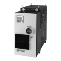
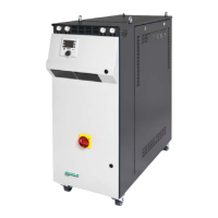
Identifies key spare parts on the 90M model using visual labels.
Highlights key components and their labels for the 90M/DK model.
Shows labels for components of the 90M/1K and 90M/2K models.
Identifies key components for the P140M/1K and P140M/2K models.
Shows labels for components of the P140M/SK and P140M/2SK models.
Identifies key components for the P160M(D)/1K and P160M(D)/2K models.
Shows labels for components of the P160M(D)/SK and P160M(D)/2SK models.
Provides a table listing part numbers, articles, and their English item descriptions.
Identifies electrical components like lamps, pumps, switches, and relays.
Details mechanical parts of the pump, including seals, casings, and impellers.
Shows diagrams and lists replacement parts for the pump head and motor with magnetic drive.
Provides a breakdown and part list for the EV220B 1/2" solenoid valve.
Details the components and parts of the EV210B 1/4"-3/8" solenoid valve.
Explains correct float switch orientation for proper level control function.
Details the procedure for checking the safety valve's function and cleaning it.
Provides a detailed drawing with dimensions and component labels for 90M and P140M models.
Presents a drawing with overall dimensions and component labels for the P160MD model.
| Pump capacity | 40 l/min |
|---|---|
| Accuracy | ±0.5°C |
| Display | Digital |
| Control Type | PID |
| Temperature Range | 20°C to 90°C |