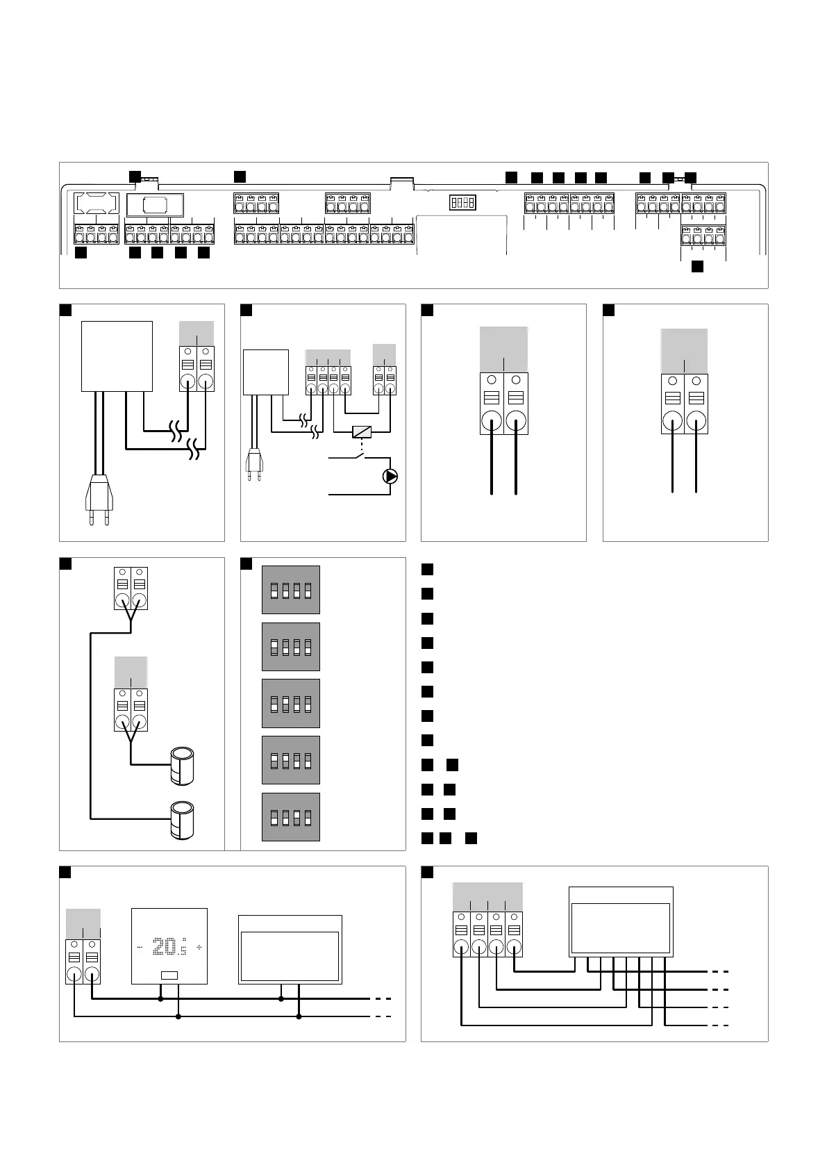
10.3 Allocation of the clamps
10.3.1 NEA SMART 2.0 Base 24 V
DI 1
RZ1
L1
IN 24V ~ OUT 24V ~
L2 L1´ L2´
RELAY 1 RELAY 4RELAY 2 RELAY 3
RZ2 RZ3 RZ4 RZ5 RZ6 RZ7 RZ8
DI 2 DI 3 DI 4
ZOBUS 2
ZOBUS 1
GND 1 2 VDC
SYSBUS
GND 1 2 VDC
SYSBUS
A B C D E
F
G
H
I J K L M M’ O
O
T2A
5 A, Class 2
L1
L2
24 V AC
230 V AC
Transformator
A
RELAY 1
L1 L2
24 V AC
24 V Relais
L
N
230V
L1´ L2´
230 V AC
Transformator
B
RELAY 2
Boiler
C
RELAY 3
Chiller
D
RZ1
G
1
ON DIP
2 3 4
Base Master
1
ON DIP
2 3 4
Base Slave 1
1
ON DIP
2 3 4
Base Slave 2
1
ON DIP
2 3 4
Base Slave 3
1
ON DIP
2 3 4
Base Slave 4
H
A
Power supply
B
Relay 1 – pump
C
Relay 2 – boiler
D
Relay 3 – chiller
E
Relays 4
F
Glass tube fuse
G
Room zone 1 – 8
H
DIP switch for SYSBUS address
I
–
L
Digital input 1 – 4
M
/
M'
ZOBUS for R-Modules and Room unit
O
/
O'
SYSBUS for U-Module and additional Bases (slaves)
E
,
J
–
L
Freely configurable
ZOBUS
Room
Unit
R-Module
…
1 2
M
2 VDC
SYSBUS
GND 1
U-Module
…
O
Fig. 10-1 Allocation of the clamps - NEA SMART 2.0 Base 24 V
105
 Loading...

